Stabilizer (aeronautics)
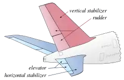
An aircraft stabilizer is an aerodynamic surface, typically including one or more movable control surfaces,[1][2] that provides longitudinal (pitch) and/or directional (yaw) stability and control. A stabilizer can feature a fixed or adjustable structure on which any movable control surfaces are hinged, or it can itself be a fully movable surface such as a stabilator. Depending on the context, "stabilizer" may sometimes describe only the front part of the overall surface.

In the conventional aircraft configuration, separate vertical (fin) and horizontal (tailplane) stabilizers form an empennage positioned at the tail of the aircraft. Other arrangements of the empennage, such as the V-tail configuration, feature stabilizers which contribute to a combination of longitudinal and directional stabilization and control.
Longitudinal stability and control may be obtained with other wing configurations, including canard, tandem wing and tailless aircraft.
Some types of aircraft are stabilized with electronic flight control; in this case, fixed and movable surfaces located anywhere along the aircraft may serve as active motion dampers or stabilizers.
Horizontal stabilizers

A horizontal stabilizer is used to maintain the aircraft in longitudinal balance, or trim:[3] it exerts a vertical force at a distance so the summation of pitch moments about the center of gravity is zero.[4] The vertical force exerted by the stabilizer varies with flight conditions, in particular according to the aircraft lift coefficient and wing flaps deflection which both affect the position of the center of pressure, and with the position of the aircraft center of gravity (which changes with aircraft loading and fuel consumption). Transonic flight makes special demands on horizontal stabilizers; when the local speed of the air over the wing reaches the speed of sound there is a sudden move aft of the center of pressure.
Another role of a horizontal stabilizer is to provide longitudinal static stability. Stability can be defined only when the vehicle is in trim;[5] it refers to the tendency of the aircraft to return to the trimmed condition if it is disturbed.[6] This maintains a constant aircraft attitude, with unchanging pitch angle relative to the airstream, without active input from the pilot. Ensuring static stability of an aircraft with a conventional wing requires that the aircraft center of gravity be ahead of the center of pressure, so a stabilizer positioned at the rear of the aircraft will produce lift in the downwards direction.
The elevator serves to control the pitch axis; in case of a fully movable tail, the entire assembly acts as a control surface.
Wing-stabilizer interaction
The upwash and downwash associated with the generation of lift is the source of aerodynamic interaction between the wing and stabilizer, which translates into a change in the effective angle of attack for each surface. The influence of the wing on a tail is much more significant than the opposite effect and can be modeled using the Prandtl lifting-line theory; however, an accurate estimation of the interaction between multiple surfaces requires computer simulations or wind tunnel tests.[7]
Conventional tailplane

In the conventional configuration the horizontal stabilizer is a small horizontal tail or tailplane located to the rear of the aircraft. This is the most common configuration.
On many aircraft, the tailplane assembly consists of a fixed surface fitted with a hinged aft elevator surface. Trim tabs may be used to relieve pilot input forces; conversely in some cases, such as small aircraft with all-moving stabilizers, anti-servo tabs are used to increase these forces.
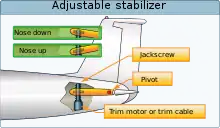
Most airliners and transport aircraft feature a large, slow-moving trimmable tail plane which is combined with independently-moving elevators. The elevators are controlled by the pilot or autopilot and primarily serve to change the aircraft's attitude, while the whole assembly is used to trim (maintaining horizontal static equilibrium) and stabilize the aircraft in the pitch axis.
Many supersonic aircraft feature an all-moving tail assembly, also named stabilator, where the entire surface is adjustable.[8]
Variants on the conventional configuration include the T-tail, Cruciform tail, Twin tail and Twin-boom mounted tail.
Three-surface aircraft

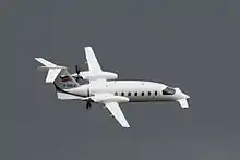
Three-surface aircraft such as the Piaggio P.180 Avanti or the Scaled Composites Triumph and Catbird, the tailplane is a stabilizer as in conventional aircraft; the frontplane, called foreplane or canard, provides lift and serves as a balancing surface.
Some earlier three-surface aircraft, such as the Curtiss AEA June Bug or the Voisin 1907 biplane, were of conventional layout with an additional front pitch control surface which was called "elevator" or sometimes "stabilisateur".[9] Lacking elevators, the tailplanes of these aircraft were not what is now called conventional stabilizers. For example, the Voisin was a tandem-lifting layout (main wing and rear wing) with a foreplane that was neither stabilizing nor mainly lifting; it was called an "équilibreur" ("balancer"),[10] and used as a pitch control and trim surface.
Canard aircraft

In the canard configuration, a small wing, or foreplane, is located in front of the main wing. Some authors call it a stabilizer [11] [12] [13][14] or give to the foreplane alone a stabilizing role, [15] although as far as pitch stability is concerned, a foreplane is generally described as a destabilizing surface, [16] the main wing providing the stabilizing moment in pitch. [17] [18] [19]
In naturally unstable aircraft, the canard surfaces may be used as an active part of the artificial stability system, and are sometimes named horizontal stabilizers.[20]
Tailless aircraft

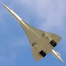
Tailless aircraft lack a separate horizontal stabilizer. In a tailless aircraft, the horizontal stabilizing surface is part of the main wing.[21][22] Longitudinal stability in tailless aircraft is achieved by designing the aircraft so that its aerodynamic center is behind the center of gravity. This is generally done by modifying the wing design, for example by varying the angle of incidence in the span-wise direction (wing washout or twist), or by using reflexed camber airfoils.
Vertical stabilizers
A vertical stabilizer provides directional (or yaw) stability and usually comprises a fixed fin and movable control rudder hinged to its rear edge.[23] Less commonly, there is no hinge and the whole fin surface is pivoted for both stability and control.[24]
When an aircraft encounters a horizontal gust of wind, yaw stability causes the aircraft to turn into the wind, rather than turn in the same direction.[25]
Fuselage geometry, engine nacelles and rotating propellers all influence lateral static stability and affect the required size of the stabilizer.[26]
If an aircraft does not have a vertical stabilizer then that aircraft is almost unmaneuverable.
Tailless directional stabilization and control
Although the use of a vertical stabilizer is most common, it is possible to obtain directional stability with no discrete vertical stabilizer. This occurs when the wing is swept back and in some cases, as for example on the Rogallo wing often used for hang gliders, means that no fin is needed.
- Stabilization. When a swept wing is rotated in yaw the outer wing sweep is reduced, so increasing drag, while the inner wing sweep increases, reducing drag. This change in the drag distribution creates a restoring moment.
- Control. A way to get yaw control is to use differential air braking to affect the drag directly. This technique is suited to Electronic flight controls, as on the Northrop Grumman B-2 flying wing.[27]
Combined longitudinal - directional stabilizers

On some aircraft, horizontal and vertical stabilizers are combined in a pair of surfaces named V-tail. In this arrangement, two stabilizers (fins and rudders) are mounted at 90 - 120° to each other,[note 1] giving a larger horizontal projected area than vertical one as in the majority of conventional tails. The moving control surfaces are then named ruddervators.[28][note 2] The V-tail thus acts both as a yaw and pitch stabilizer.
Although it may seem that the V-tail configuration can result in a significant reduction of the tail wetted area, it suffers from an increase in control-actuation complexity,[28] as well as complex and detrimental aerodynamic interaction between the two surfaces.[29] This often results in an upsizing in the total area that reduces or negates the original benefit.[28] The Beechcraft Bonanza light aircraft was originally designed with a V-tail.
Others combined layouts exist. The General Atomics MQ-1 Predator unmanned aircraft has an inverted V-tail. The tail surfaces of the Lockheed XFV could be described as a V-tail with surfaces that extended through the fuselage to the opposite side. The LearAvia Lear Fan had a Y-tail. All twin tail arrangements with a tail dihedral angle will provide a combination of longitudinal and directional stabilization.
Notes
- F-117 Nighthawk, 90° - Fouga Magister, 105° - Beech Bonanza, 116°
- A portmanteau of rudder & elevator
References
- Empennage - D. Stinton The design of the aeroplane, Longitudinal stability - Hoerner Fluid Dynamic Lift - Ilan Kroo, Aircraft Design. In stability considerations (tail sizing, tail area, stabiliser volume coefficient), authors always deal with the whole unit, that includes elevators. "Horizontal tail" or "tail" terms are generally used in lieu of "stabilizer".
- Roskam, Jan (2002). Airplane Design: Pt. 3. Lawrence: DARcorporation. p. 287. ISBN 1-884885-56-X. Retrieved 30 July 2015.
- Daroll Stinton, The design of the aeroplane, "Longitudinal balance (trim)".
- Phillips, Warren F. (2010). "4.1 Fundamentals of Static Equilibrium and Stability". Mechanics of Flight (2nd ed.). Hoboken, New Jersey: Wiley & Sons. p. 377. ISBN 978-0-470-53975-0.
When the controls are set so that the resultant forces and the moments about the center of gravity are all zero, the aircraft is said to be in trim, which simply means static equilibrium
- W.H. Phillips, A Career at NASA Langley Research Center, Chap.4, Flying Qualities
- Phillips, Warren F. (2010). "4.2 Pitch Stability of a Cambered Wing". Mechanics of Flight (2nd ed.). Hoboken, New Jersey: Wiley & Sons. p. 381. ISBN 978-0-470-53975-0.
For an airplane to be statically stable in rotation, any disturbances in roll, pitch or yaw must all result in the production of a restoring moment that will return the aircraft to the original equilibrium state.
- Phillips, Warren F. (2010). "4.3 Simplified Pitch Stability Analysis for a Wing-Tail Combination". Mechanics of Flight (2nd ed.). Hoboken, New Jersey: Wiley & Sons. p. 391. ISBN 978-0-470-53975-0.
- "Horizontal stabilizer - elevator", The Beginner's Guide to Aeronautics, NASA Glenn Research Center, Sep 13, 2010
- Gérard Hartmann (12 May 2003), "Les hydros Farman" (PDF), Dossiers historiques et technique aéronautique française,
le stabilisateur avant sera supprimé en cours d'année ("the front stabilizer will be removed during the year")
- Gabriel Voisin, Mes 10.000 cerfs-volants (My 10,000 kites), page 166: "et je m'apprêtais à tirer sur mon équilibreur... puis il braqua son équilibreur vers la montée."
- Garrison, P; "Three's Company"; Flying 129 (12), December 2002, pp.85-86: "the stabilizer in the front" ... "This is the function of the stabilizer. if it's in the back it typically pushes downward, and if it's in the front it lifts upward."
- Benson, T (Ed): "Airplane parts and functions", Beginner's Guide to Aeronautics, NASA Glenn Research Center,
On the Wright brother's first aircraft, the horizontal stabilizer was placed in front of the wings.
- US Patent US 6064923 A, Aircraft with reduced wing structure loading: "...a front stabilizer, generally known as a canard stabilizer,"
- "Parts of Airplane", The Beginner's Guide to Aeronautics, NASA Glenn Research Center
- Horizontal stabilizer - elevator, NASA,
On some aircraft, the pitch stability and control is provided by a horizontal surface placed forward of the center of gravity
- e.g. In AIR International May 1999, p.311, Hoerner and Borst, Fluid Dynamic Lift, page 11-29, and Page 11-33 Delta canard, NASA TM 88354, A look at handling qualities of canard configurations, p. 14 and Kundu, Aircraft Design, Page 92,
- Phillips, Warren F. (2010). "4.6 Simplified Pitch Stability Analysis for a Wing-Canard Combination". Mechanics of Flight (2nd ed.). Hoboken, New Jersey: Wiley & Sons. p. 425. ISBN 978-0-470-53975-0.
…it is the main wing and not the canard that provides stability for the wing-canard configuration.
- AIAA/AHS/ASEE Aircraft Design, Systems and Operations Meeting: ... - Volume 2 - Page 309, "Pitching-moment results show the stabilising effect of the wing and the destabilizing effect of the canard."
- F.H. Nichols,The Effects of Wing Vertical Location and Vertical-tail Arrangement on the Stability Characteristics of Canard Airplane Configurations, page 9, "The body also produces a substantial destabilizing component which is adequately balanced by the large stabilizing effect of the wing."
- The X-29 ... while its canards — horizontal stabilizers to control pitch — were in front of the wings instead of on the tail"
- Theory and Practice of Using Flying Wings, Apogee Components
- Notes on the stability and control of tailless airplanes, Jones, Robert, naca-tn-837, 1941
- Daroll Stinton, The design of the aeroplane, lateral and directional stability and spinning
- Barnard, R.H.; Philpott, D.R. (2010). "10. Aircraft control". Aircraft Flight (4th ed.). Harlow, England: Prentice Hall. p. 271. ISBN 978-0-273-73098-9.
- Barber, Horatio, "Chapter II - Stability and Control", The Aeroplane Speaks, Electronic Text Center, University of Virginia Library
- Phillips, Warren F. (2010). "5 Lateral Static Stability and Trim". Mechanics of Flight (2nd ed.). Hoboken, New Jersey: Wiley & Sons. ISBN 978-0-470-53975-0.
- Sweetman, Bill (2005). Lockheed Stealth. North Branch, Minnesota: Zenith Imprint. p. 73. ISBN 0-7603-1940-5.
- Raymer, Daniel P. (1999). "4.5 Tail Geometry and Arrangement". Aircraft Design: A Conceptual Approach (3rd ed.). Reston, Virginia: American Institute of Aeronautics and Astronautics. p. 78. ISBN 1-56347-281-3.
- Phillips, Warren F. (2010). "5.5 Effects of Tail Dihedral on Yaw Stability". Mechanics of Flight (2nd ed.). Hoboken, New Jersey: Wiley & Sons. p. 533. ISBN 978-0-470-53975-0.
External links
- Aircraft-related terminology
- Talay, Theodore A. (27 January 2005). "Introduction to the Aerodynamics of Flight – Stability and Control". NASA History Division. Langley Research Center. Retrieved 21 April 2013.
- "Dynamic Longitudinal, Directional, and Lateral Stability", Centennial of Flight, US Centennial of Flight Commission