Lathe
A lathe (/leɪð/) is a machine tool that rotates a workpiece about an axis of rotation to perform various operations such as cutting, sanding, knurling, drilling, deformation, facing, and turning, with tools that are applied to the workpiece to create an object with symmetry about that axis.[1]

a – bed
b – carriage (with cross-slide and tool post)
c – headstock
d – back gear (other gear train nearby drives lead screw)
e – cone pulley for a belt drive from an external power source
f – faceplate mounted on spindle
g – tailstock
h – leadscrew

Uses
Lathes are used in woodturning, metalworking, metal spinning, thermal spraying, parts reclamation, and glass-working. Lathes can be used to shape pottery, the best-known design being the Potter's wheel. Most suitably equipped metalworking lathes can also be used to produce most solids of revolution, plane surfaces and screw threads or helices. Ornamental lathes can produce three-dimensional solids of incredible complexity. The workpiece is usually held in place by either one or two centers, at least one of which can typically be moved horizontally to accommodate varying workpiece lengths. Other work-holding methods include clamping the work about the axis of rotation using a chuck or collet, or to a faceplate, using clamps or dog clutch.
Products made by lathes
Examples of objects that can be produced on a lathe include screws, candlesticks, gun barrels, cue sticks, table legs, bowls, baseball bats, musical instruments (especially woodwind instruments), crankshafts and much more.
History


The lathe is an ancient tool. The earliest evidence of a lathe dates back to Ancient Egypt around 1300 BC.[2] There is also tenuous evidence for its existence at a Mycenaean Greek site, dating back as far as the 13th or 14th century BC.[3]
Clear evidence of turned artifacts have been found from the 6th century BC: fragments of a wooden bowl in an Etruscan tomb in Northern Italy as well as two flat wooden dishes with decorative turned rims from modern Turkey.[4]
During the Warring States period in China, c. 400 BCE, the ancient Chinese used rotary lathes to sharpen tools and weapons on an industrial scale.[5]
The first known painting showing a lathe dates to the 3rd century BC in ancient Egypt.[6]
The lathe was very important to the Industrial Revolution. It is known as the mother of machine tools, as it was the first machine tool that led to the invention of other machine tools.[7] The first fully documented, all-metal slide rest lathe was invented by Jacques de Vaucanson around 1751. It was described in the Encyclopédie.

In 1718 Russian engineer Andrey Nartov invented one of the first lathes with a mechanical cutting tool-supporting carriage and a set of gears (also known as a compound rest or slide rest) with the first to invent such a lathe probably being Leonardo da Vinci.[8]
An important early lathe in the UK was the horizontal boring machine that was installed by Jan Verbruggen in 1772 in the Royal Arsenal in Woolwich. It was horse-powered and allowed for the production of much more accurate and stronger cannon used with success in the American Revolutionary War in the late 18th century. One of the key characteristics of this machine was that the workpiece was turning as opposed to the tool, making it technically a lathe. Henry Maudslay, who later developed many improvements to the lathe, worked at the Royal Arsenal from 1783, being exposed to this machine in the Verbruggen workshop.[9] A detailed description of Vaucanson's lathe was published decades before Maudslay perfected his version. It is likely that Maudslay was not aware of Vaucanson's work, since his first versions of the slide rest had many errors that were not present in the Vaucanson lathe.
During the Industrial Revolution, mechanized power generated by water wheels or steam engines was transmitted to the lathe via line shafting, allowing faster and easier work. Metalworking lathes evolved into heavier machines with thicker, more rigid parts. Between the late 19th and mid-20th centuries, individual electric motors at each lathe replaced line shafting as the power source. Beginning in the 1950s, servomechanisms were applied to the control of lathes and other machine tools via numerical control, which often was coupled with computers to yield computerized numerical control (CNC). Today manually controlled and CNC lathes coexist in the manufacturing industries.
Description
Parts
A lathe may or may not have legs also known as a nugget, which sit on the floor and elevate the lathe bed to a working height. A lathe may be small and sit on a workbench or table, not requiring a stand.
Almost all lathes have a bed, which is (almost always) a horizontal beam (although CNC lathes commonly have an inclined or vertical beam for a bed to ensure that swarf, or chips, falls free of the bed). Woodturning lathes specialized for turning large bowls often have no bed or tail stock, merely a free-standing headstock and a cantilevered tool rest.
At one end of the bed (almost always the left, as the operator faces the lathe) is a headstock. The headstock contains high-precision spinning bearings. Rotating within the bearings is a horizontal axle, with an axis parallel to the bed, called the spindle. Spindles are often hollow and have an interior Morse taper on the spindle nose (i.e., facing to the right / towards the bed) by which work-holding accessories may be mounted to the spindle. Spindles may also have arrangements for work-holding on the left-hand end of the spindle with other tooling arrangements for particular tasks. (i.e., facing away from the main bed) end, or may have a hand-wheel or other accessory mechanism on their outboard end. Spindles are powered and impart motion to the workpiece.
The spindle is driven either by foot power from a treadle and flywheel or by a belt or gear drive from a power source such as electric motor or overhead line shafts. In most modern lathes this power source is an integral electric motor, often either in the headstock, to the left of the headstock, or beneath the headstock, concealed in the stand.
In addition to the spindle and its bearings, the headstock often contains parts to convert the motor speed into various spindle speeds. Various types of speed-changing mechanism achieve this, from a cone pulley or step pulley, to a cone pulley with back gear (which is essentially a low range, similar in net effect to the two-speed rear of a truck), to an entire gear train similar to that of a manual-shift automotive transmission. Some motors have electronic rheostat-type speed controls, which obviates cone pulleys or gears.
The counterpoint to the headstock is the tailstock, sometimes referred to as the loose head, as it can be positioned at any convenient point on the bed by sliding it to the required area. The tail-stock contains a barrel, which does not rotate, but can slide in and out parallel to the axis of the bed and directly in line with the headstock spindle. The barrel is hollow and usually contains a taper to facilitate the gripping of various types of tooling. Its most common uses are to hold a hardened steel center, which is used to support long thin shafts while turning, or to hold drill bits for drilling axial holes in the work piece. Many other uses are possible.[10]
Metalworking lathes have a carriage (comprising a saddle and apron) topped with a cross-slide, which is a flat piece that sits crosswise on the bed and can be cranked at right angles to the bed. Sitting atop the cross slide is usually another slide called a compound rest, which provides 2 additional axes of motion, rotary and linear. Atop that sits a toolpost, which holds a cutting tool, which removes material from the workpiece. There may or may not be a leadscrew, which moves the cross-slide along the bed.
Woodturning and metal spinning lathes do not have cross-slides, but rather have banjos, which are flat pieces that sit crosswise on the bed. The position of a banjo can be adjusted by hand; no gearing is involved. Ascending vertically from the banjo is a tool-post, at the top of which is a horizontal tool-rest. In woodturning, hand tools are braced against the tool rest and levered into the workpiece. In metal spinning, the further pin ascends vertically from the tool rest and serves as a fulcrum against which tools may be levered into the workpiece.
Accessories
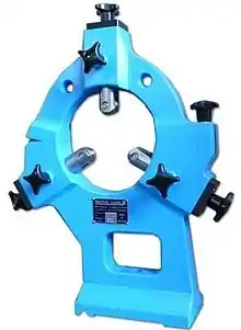
Unless a workpiece has a taper machined onto it which perfectly matches the internal taper in the spindle, or has threads which perfectly match the external threads on the spindle (two conditions which rarely exist), an accessory must be used to mount a workpiece to the spindle.
A workpiece may be bolted or screwed to a faceplate, a large, flat disk that mounts to the spindle. In the alternative, faceplate dogs may be used to secure the work to the faceplate.
A workpiece may be mounted on a mandrel, or circular work clamped in a three- or four-jaw chuck. For irregular shaped workpieces it is usual to use a four jaw (independent moving jaws) chuck. These holding devices mount directly to the lathe headstock spindle.
In precision work, and in some classes of repetition work, cylindrical workpieces are usually held in a collet inserted into the spindle and secured either by a draw-bar, or by a collet closing cap on the spindle. Suitable collets may also be used to mount square or hexagonal workpieces. In precision toolmaking work such collets are usually of the draw-in variety, where, as the collet is tightened, the workpiece moves slightly back into the headstock, whereas for most repetition work the dead length variety is preferred, as this ensures that the position of the workpiece does not move as the collet is tightened.
A soft workpiece (e.g., wood) may be pinched between centers by using a spur drive at the headstock, which bites into the wood and imparts torque to it.
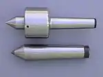
A soft dead center is used in the headstock spindle as the work rotates with the centre. Because the centre is soft it can be trued in place before use. The included angle is 60°. Traditionally, a hard dead center is used together with suitable lubricant in the tailstock to support the workpiece. In modern practice the dead center is frequently replaced by a running center, as it turns freely with the workpiece—usually on ball bearings—reducing the frictional heat, especially important at high speeds. When clear facing a long length of material it must be supported at both ends. This can be achieved by the use of a traveling or fixed steady. If a steady is not available, the end face being worked on may be supported by a dead (stationary) half center. A half center has a flat surface machined across a broad section of half of its diameter at the pointed end. A small section of the tip of the dead center is retained to ensure concentricity. Lubrication must be applied at this point of contact and tail stock pressure reduced. A lathe carrier or lathe dog may also be employed when turning between two centers.[11]
In woodturning, one variation of a running center is a cup center, which is a cone of metal surrounded by an annular ring of metal that decreases the chances of the workpiece splitting.
A circular metal plate with even spaced holes around the periphery, mounted to the spindle, is called an "index plate". It can be used to rotate the spindle to a precise angle, then lock it in place, facilitating repeated auxiliary operations done to the workpiece.
Other accessories, including items such as taper turning attachments, knurling tools, vertical slides, fixed and traveling steadies, etc., increase the versatility of a lathe and the range of work it may perform.
Modes of use
When a workpiece is fixed between the headstock and the tail-stock, it is said to be "between centers". When a workpiece is supported at both ends, it is more stable, and more force may be applied to the workpiece, via tools, at a right angle to the axis of rotation, without fear that the workpiece may break loose.
When a workpiece is fixed only to the spindle at the headstock end, the work is said to be "face work". When a workpiece is supported in this manner, less force may be applied to the workpiece, via tools, at a right angle to the axis of rotation, lest the workpiece rip free. Thus, most work must be done axially, towards the headstock, or at right angles, but gently.
When a workpiece is mounted with a certain axis of rotation, worked, then remounted with a new axis of rotation, this is referred to as "eccentric turning" or "multi-axis turning". The result is that various cross sections of the workpiece are rotationally symmetric, but the workpiece as a whole is not rotationally symmetric. This technique is used for camshafts, various types of chair legs.
Sizes
Lathes are usually 'sized' by the capacity of the work that they may hold. Usually large work is held at both ends either using a chuck or other drive in the headstock and a centre in the tailstock. To maximise size, turning between centres allows the work to be as close to the headstock as possible and is used to determine the longest piece the lathe will turn - when the base of the tailstock is aligned with the end of the bed. The distance between centres gives the maximum length of work the lathe will officially hold. It is possible to get slightly longer items in if the tailstock overhangs the end of the bed but this is an ill-advised practice.
The other dimension of the workpiece is how far off-centre it can be. This is known as the 'swing' ("The distance from the head center of a lathe to the bed or ways, or to the rest. The swing determines the diametric size of the object which is capable of being turned in the lathe; anything larger would interfere with the bed. This limit is called the swing of the bed. The swing of the rest is the size which will rotate above the rest, which lies upon the bed.")[12] from the notion that the work 'swings' from the centre upon which it is mounted. This makes more sense with odd-shaped work but as the lathe is most often used with cylindrical work, it is useful to know the maximum diameter of work the lathe will hold. This is simply the value of the swing (or centre height above the bed) multiplied by two. For some reason, in the U.S. swing is assumed to be diameter but this is incorrect. To be clear on size, it is better, therefore, to describe the dimension as 'centre height above the bed'. As parts of the lathe reduce capacity, measurements such as 'swing over cross slide' or other named parts can be found.
Varieties
The smallest lathes are "jewelers lathes" or "watchmaker lathes", which, though often small enough to be held in one hand are normally fastened to a bench. The workpieces machined on a jeweler's lathe are often metal, but other softer materials can also be machined. Jeweler's lathes can be used with hand-held "graver" tools or with a "compound rest" that attach to the lathe bed and allows the tool to be clamped in place and moved by a screw or lever feed. Graver tools are generally supported by a T-rest, not fixed to a cross slide or compound rest. The work is usually held in a collet, but high-precision 3 and 6-jaw chucks are also commonly employed. Common spindle bore sizes are 6 mm, 8 mm and 10 mm. The term WW refers to the Webster/Whitcomb collet and lathe, invented by the American Watch Tool Company of Waltham, Massachusetts. Most lathes commonly referred to as watchmakers lathes are of this design. In 1909, the American Watch Tool company introduced the Magnus type collet (a 10-mm body size collet) using a lathe of the same basic design, the Webster/Whitcomb Magnus. (F.W.Derbyshire, Inc. retains the trade names Webster/Whitcomb and Magnus and still produces these collets.) Two bed patterns are common: the WW (Webster Whitcomb) bed, a truncated triangular prism (found only on 8 and 10 mm watchmakers' lathes); and the continental D-style bar bed (used on both 6 mm and 8 mm lathes by firms such as Lorch and Star). Other bed designs have been used, such a triangular prism on some Boley 6.5 mm lathes, and a V-edged bed on IME's 8 mm lathes.
Smaller metalworking lathes that are larger than jewelers' lathes and can sit on a bench or table, but offer such features as tool holders and a screw-cutting gear train are called hobby lathes, and larger versions, "bench lathes" - this term also commonly applied to a special type of high-precision lathe used by toolmakers for one-off jobs.[13] Even larger lathes offering similar features for producing or modifying individual parts are called "engine lathes". Lathes of these types do not have additional integral features for repetitive production, but rather are used for individual part production or modification as the primary role.
Lathes of this size that are designed for mass manufacture, but not offering the versatile screw-cutting capabilities of the engine or bench lathe, are referred to as "second operation" lathes.
Lathes with a very large spindle bore and a chuck on both ends of the spindle are called "oil field lathes".
Fully automatic mechanical lathes, employing cams and gear trains for controlled movement, are called screw machines.
Lathes that are controlled by a computer are CNC lathes.
Lathes with the spindle mounted in a vertical configuration, instead of horizontal configuration, are called vertical lathes or vertical boring machines. They are used where very large diameters must be turned, and the workpiece (comparatively) is not very long.
A lathe with a tool post that can rotate around a vertical axis, so as to present different tools towards the headstock (and the workpiece) are turret lathes.[14]
A lathe equipped with indexing plates, profile cutters, spiral or helical guides, etc., so as to enable ornamental turning is an ornamental lathe.
Various combinations are possible: for example, a vertical lathe can have CNC capabilities as well (such as a CNC VTL).
Lathes can be combined with other machine tools, such as a drill press or vertical milling machine. These are usually referred to as combination lathes.
Major categories
Woodworking lathes
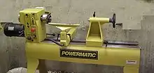
Woodworking lathes are the oldest variety. All other varieties are descended from these simple lathes. An adjustable horizontal metal rail – the tool rest – between the material and the operator accommodates the positioning of shaping tools, which are usually hand-held. After shaping, it is common practice to press and slide sandpaper against the still-spinning object to smooth the surface made with the metal shaping tools. The tool rest is usually removed during sanding, as it may be unsafe to have the operators hands between it and the spinning wood.
Many woodworking lathes can also be used for making bowls and plates. The bowl or plate needs only to be held at the bottom by one side of the lathe. It is usually attached to a metal face plate attached to the spindle. With many lathes, this operation happens on the left side of the headstock, where are no rails and therefore more clearance. In this configuration, the piece can be shaped inside and out. A specific curved tool rest may be used to support tools while shaping the inside. Further detail can be found on the woodturning page.
Most woodworking lathes are designed to be operated at a speed of between 200 and 1,400 revolutions per minute, with slightly over 1,000 rpm considered optimal for most such work, and with larger workpieces requiring lower speeds.[15]
Duplicating lathes
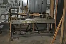
One type of specialized lathe is duplicating or copying lathe also known as Blanchard lathe after its inventor Thomas Blanchard. This type of lathe was able to create shapes identical to a standard pattern and it revolutionized the process of gun stock making in the 1820s when it was invented.[16]
Patternmaker's lathes
.jpg.webp)
Used to make a pattern for foundries, often from wood, but also plastics. A patternmaker's lathe looks like a heavy wood lathe, often with a turret and either a leadscrew or a rack and pinion to manually position the turret. The turret is used to accurately cut straight lines. They often have a provision to turn very large parts on the other end of the headstock, using a free-standing toolrest. Another way of turning large parts is a sliding bed, which can slide away from the headstock and thus open up a gap in front of the headstock for large parts.
Metalworking lathes

In a metalworking lathe, metal is removed from the workpiece using a hardened cutting tool, which is usually fixed to a solid moveable mounting, either a tool-post or a turret, which is then moved against the workpiece using handwheels or computer-controlled motors. These cutting tools come in a wide range of sizes and shapes, depending upon their application. Some common styles are diamond, round, square and triangular.
The tool-post is operated by lead-screws that can accurately position the tool in a variety of planes. The tool-post may be driven manually or automatically to produce the roughing and finishing cuts required to turn the workpiece to the desired shape and dimensions, or for cutting threads, worm gears, etc. Cutting fluid may also be pumped to the cutting site to provide cooling, lubrication and clearing of swarf from the workpiece. Some lathes may be operated under control of a computer for mass production of parts (see "Computer numerical control").
Manually controlled metalworking lathes are commonly provided with a variable-ratio gear-train to drive the main lead-screw. This enables different thread pitches to be cut. On some older lathes or more affordable new lathes, the gear trains are changed by swapping gears with various numbers of teeth onto or off of the shafts, while more modern or expensive manually controlled lathes have a quick-change box to provide commonly used ratios by the operation of a lever. CNC lathes use computers and servomechanisms to regulate the rates of movement.
On manually controlled lathes, the thread pitches that can be cut are, in some ways, determined by the pitch of the lead-screw: A lathe with a metric lead-screw will readily cut metric threads (including BA), while one with an imperial lead-screw will readily cut imperial-unit-based threads such as BSW or UTS (UNF, UNC). This limitation is not insurmountable, because a 127-tooth gear, called a transposing gear, is used to translate between metric and inch thread pitches. However, this is optional equipment that many lathe owners do not own. It is also a larger change-wheel than the others, and on some lathes may be larger than the change-wheel mounting banjo is capable of mounting.
The workpiece may be supported between a pair of points called centres, or it may be bolted to a faceplate or held in a chuck. A chuck has movable jaws that can grip the workpiece securely.
There are some effects on material properties when using a metalworking lathe. There are few chemical or physical effects, but there are many mechanical effects, which include residual stress, micro-cracks, work-hardening, and tempering in hardened materials.
Cue lathes
Cue lathes function similarly to turning and spinning lathes, allowing a perfectly radially-symmetrical cut for billiard cues. They can also be used to refinish cues that have been worn over the years.
Glass-working lathes
Glass-working lathes are similar in design to other lathes, but differ markedly in how the workpiece is modified. Glass-working lathes slowly rotate a hollow glass vessel over a fixed- or variable-temperature flame. The source of the flame may be either hand-held or mounted to a banjo/cross-slide that can be moved along the lathe bed. The flame serves to soften the glass being worked, so that the glass in a specific area of the workpiece becomes ductile and subject to forming either by inflation ("glassblowing") or by deformation with a heat-resistant tool. Such lathes usually have two head-stocks with chucks holding the work, arranged so that they both rotate together in unison. Air can be introduced through the headstock chuck spindle for glassblowing. The tools to deform the glass and tubes to blow (inflate) the glass are usually handheld.
In diamond turning, a computer-controlled lathe with a diamond-tipped tool is used to make precision optical surfaces in glass or other optical materials. Unlike conventional optical grinding, complex aspheric surfaces can be machined easily. Instead of the dovetailed ways used on the tool slide of a metal-turning lathe, the ways typically float on air bearings, and the position of the tool is measured by optical interferometry to achieve the necessary standard of precision for optical work. The finished work piece usually requires a small amount of subsequent polishing by conventional techniques to achieve a finished surface suitably smooth for use in a lens, but the rough grinding time is significantly reduced for complex lenses.
Metal-spinning lathes
In metal spinning, a disk of sheet metal is held perpendicularly to the main axis of the lathe, and tools with polished tips (spoons) or roller tips are hand-held, but levered by hand against fixed posts, to develop pressure that deforms the spinning sheet of metal.
Metal-spinning lathes are almost as simple as wood-turning lathes. Typically, metal spinning requires a mandrel, usually made from wood, which serves as the template onto which the workpiece is formed (asymmetric shapes can be made, but it is a very advanced technique). For example, to make a sheet metal bowl, a solid block of wood in the shape of the bowl is required; similarly, to make a vase, a solid template of the vase is required.
Given the advent of high-speed, high-pressure, industrial die forming, metal spinning is less common now than it once was, but still a valuable technique for producing one-off prototypes or small batches, where die forming would be uneconomical.
Ornamental turning lathes
The ornamental turning lathe was developed around the same time as the industrial screw-cutting lathe in the nineteenth century. It was used not for making practical objects, but for decorative work – ornamental turning. By using accessories such as the horizontal and vertical cutting frames, eccentric chuck and elliptical chuck, solids of extraordinary complexity may be produced by various generative procedures.
A special-purpose lathe, the Rose engine lathe, is also used for ornamental turning, in particular for engine turning, typically in precious metals, for example to decorate pocket-watch cases. As well as a wide range of accessories, these lathes usually have complex dividing arrangements to allow the exact rotation of the mandrel. Cutting is usually carried out by rotating cutters, rather than directly by the rotation of the work itself. Because of the difficulty of polishing such work, the materials turned, such as wood or ivory, are usually quite soft, and the cutter has to be exceptionally sharp. The finest ornamental lathes are generally considered to be those made by Holtzapffel around the turn of the 19th century.
Reducing lathe
Many types of lathes can be equipped with accessory components to allow them to reproduce an item: the original item is mounted on one spindle, the blank is mounted on another, and as both turn in synchronized manner, one end of an arm "reads" the original and the other end of the arm "carves" the duplicate.
A reduction lathe is a specialized lathe that is designed with this feature and incorporates a mechanism similar to a pantograph, so that when the "reading" end of the arm reads a detail that measures one inch (for example), the cutting end of the arm creates an analogous detail that is (for example) one quarter of an inch (a 4:1 reduction, although given appropriate machinery and appropriate settings, any reduction ratio is possible).
Reducing lathes are used in coin-making, where a plaster original (or an epoxy master made from the plaster original, or a copper-shelled master made from the plaster original, etc.) is duplicated and reduced on the reducing lathe, generating a master die.
Rotary lathes
A lathe in which softwood, like spruce or pine, or hardwood, like birch, logs are turned against a very sharp blade and peeled off in one continuous or semi-continuous roll. Invented by Immanuel Nobel (father of the more famous Alfred Nobel). The first such lathes in the United States were set up in the mid-19th century. The product is called wood veneer and it is used for making plywood and as a cosmetic surface veneer on some grades of chipboard.
Watchmaker's lathes
Watchmakers lathes are delicate but precise metalworking lathes, usually without provision for screwcutting, and are still used by horologists for work such as the turning of balance staffs. A handheld tool called a graver is often used in preference to a slide-mounted tool. The original watchmaker's turns was a simple dead-center lathe with a moveable rest and two loose head-stocks. The workpiece would be rotated by a bow, typically of horsehair, wrapped around it.
Transcription, or recording, lathes
Transcription or recording lathes are used to make grooves on a surface for recording sounds. These were used in creating sound grooves on wax cylinders and then on flat recording discs originally also made of wax, but later as lacquers on a substrata. Originally the cutting lathes were driven by sound vibrations through a horn in a process known as Acoustic recording and later driven by an electric current when microphones were first used in sound recording. Many such lathes were professional models, but others were developed for home recording and were common before the advent of home tape recording.
Gallery
Examples of lathes
.jpg.webp) Treadle lathe
Treadle lathe.jpg.webp) Lathes for making gun barrels, Naval Gun Factory, Washington, D.C.
Lathes for making gun barrels, Naval Gun Factory, Washington, D.C. Large old lathe
 Small metalworking lathe
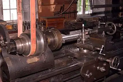 Belt-driven metalworking lathe in the machine shop at Hagley Museum
 Single Screw Lathe Machine
Examples of work produced from a lathe
 Lathe exercise
 Turned chess pieces
Performance evaluation
National and international standards are used to standardize the definitions, environmental requirements, and test methods used for the performance evaluation of lathes. Election of the standard to be used is an agreement between the supplier and the user and has some significance in the design of the lathe. In the United States, ASME has developed the B5.57 Standard entitled "Methods for Performance Evaluation of Computer Numerically Controlled Lathes and Turning Centers", which establishes requirements and methods for specifying and testing the performance of CNC lathes and turning centers.[17]
See also
References
- Lathes in Chapter 7 of US Army Training Circulation published in 1996 (Chemical Engineering Department, Carnegie Melon University website)
- "What is a Lathe Machine? History, Parts, and Operation". Brighthub Engineering. Retrieved 26 March 2018.
- Clifford, Brian. "A brief history of woodturning". The Woodturner's Workshop. Woodturners' Guild of Ontario. Retrieved 2018-07-24.
the first evidence of the lathe itself comes from the 3rd century BC but it is known that it was in use long before that. A flat wooden dish which stood on wooden legs was found in a pit grave at Mycenae dated at 1100 to 1400 BC...[evidence from the artifcat] suggests that it could have been turned on a mandrel held between centres in a lathe. Against this view must be set the fact that there is no sign of turned grooves on the piece
- Clifford, Brian. "A brief history of woodturning". The Woodturner's Workshop. Woodturners' Guild of Ontario. Retrieved 2018-07-24.
The earliest piece from that [Northern Italy] was found at a site known as the 'Tomb of the Warrior' at Corneto. This is a fragment of a wooden bowl, dated at around 700 BC, which shows 'clear evidence of rounding and polishing on its outer surface and of hollow turning...' (Woodbury) Other Etruscan turned vessels were found on this site. ... Excavations of a mound grave in Asia Minor (now Turkey) revealed two flat wooden dishes with decorative turned rims. These have been dated as from the 7th century BC.
- Emperor's Ghost Army (Documentary). PBS. Event occurs at 26:00. Archived from the original on 2016-01-15.
- Clifford, Brian. "A brief history of woodturning". The Woodturner's Workshop. Woodturners' Guild of Ontario. Retrieved 2018-07-24.
The earliest information on the lathe dates from the 3rd century BC. This is a bas-relief carving on the wall of the grave of an Egyptian called Petrosiris.
- Murthy, S. Trymbaka (2010). Textbook of Elements of Mechanical Engineering. ISBN 978-9380578576.
- https://books.google.co.uk/books?id=yohhbGnoHagC&pg=PA14&lpg=PA14&dq=da+Vinci+Slide+Rest+Lathe&source=bl&ots=Y_iyEXsam6&sig=ACfU3U3lD4ChJ1uhZH584wE4VjymNo6JeA&hl=en&sa=X&ved=2ahUKEwig67b1wrPqAhWST8AKHUGzCB8Q6AEwEXoECAEQAQ#v=onepage&q=da%20Vinci%20Slide%20Rest%20Lathe&f=false
- Tomiyama, Testuo (2016-02-16). "Development of Production Technology and Machine Tools (presentation notes)" (PDF). OpenCourseWare: TUDelft. TUDelft. pp. 18–21. Archived (PDF) from the original on 2018-07-25. Retrieved 2018-07-24.
1770 Jan Verbruggen Escaped to England with his Son Pieter Verbruggen (1734-1786) and Became Master Founder at Woolwich Arsenal
Tomiyama, Testuo (2011). 02. Ontwikkeling Fabricagetechnologie [02. Development of Manufacturing Technology] (Lecture). Delft, Netherlands: TUDelft. - Ruttan, Howard. "Wait a minute..." Archived from the original on 2009-01-08.
- "Hints & Tips for Using a Lathe". “George Wilson’s” Hints and Tips - Publication date unknown. Lathes.co.uk. Archived from the original on 1 December 2010. Retrieved 29 November 2010.
- Knight, Edward H. (1875). The Practical Dictionary of Mechanics. London / U.S.: Cassell & co / Houghton Mifflin. p. 2469.
- Griffiths, Tony. "Makers of "Bench Precision" Lathes". LATHES.CO.UK. Archived from the original on 27 December 2017. Retrieved 5 February 2018.
- Parker, Dana T. Building Victory: Aircraft Manufacturing in the Los Angeles Area in World War II, p. 81, 123, Cypress, CA, 2013. ISBN 978-0-9897906-0-4.
- Ernie Conover (2000), Turn a Bowl with Ernie Conover: Getting Great Results the First Time Around, Taunton, p. 16, ISBN 978-1-56158-293-8
- Smith, Merritt Roe (2015). Harpers Ferry Armory and the New Technology: The Challenge of Change. Cornell University Press. ISBN 9780801454394. Retrieved 30 June 2016.
- "Methods for Performance Evaluation of Computer Numerically Controlled Lathes and Turning Centers". asme.org. The American Society of Mechanical Engineers. Archived from the original on 7 November 2017. Retrieved 5 February 2018.
Further reading
- Holtzapffel, Charles (1843–1897). Turning and Mechanical Manipulation Volume V.
- Marlow, Frank (2008). Machine Shop Essentials: Q & A. Metal Arts Press. ISBN 978-0-9759963-3-1.
- Oscar E. Perrigo. Modern American Lathe Practice. A New, Complete and Practical Work on the "king of Machine Shop Tools.", 1907.
- Raffan, Richard (2001). Turning Wood With Richard Raffan. Taunton. ISBN 1-56158-417-7.
- Joshua Rose. The Complete Practical Machinist: Embracing Lathe Work, Vise Work, Drills, etc., Philadelphia: H.C. Baird & Co., 1876; 2nd ed. 1885.
- Sparey, Lawrence (1947). The Amateur's Lathe. Special Interest Model Books. ISBN 0-85242-288-1.
- Woodbury, Robert S (1961). History of the Lathe to 1850. Cleveland, Ohio: Society for the History of Technology. ISBN 978-0-262-73004-4.
- Bray, Stan (2004). The compact lathe (2nd rev. ed.). Poole: Special Interest Model Books. ISBN 1854862278. OCLC 63184337.
External links
| Wikimedia Commons has media related to Lathes. |
- Lathe Machine Operations
- Machine Tool Archive
- Medieval and Renaissance lathes at the Wayback Machine (archived 2017-11-10)
- The history of the lathe at Archive.today (archived 2012-12-23). Additional archives: 2016-12-01.
- Early Wood-Working
- Spring pole lathe
- Modern Machine Shop Practice a historic Victorian text describing lathe design, construction and use in the 1880s.
- The South Bend Lathe Library Make Magazine, November 16, 2011. Links to How to Run a Lathe and other publications by South Bend Lathe Works.
- "The Forgotten Power Tool." Popular Science, December 1959, pp. 149–152.
- "Disc Cutting and Recording Lathes." http://www.aes.org/aeshc/docs/recording.technology.history/lathe.html.