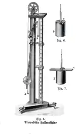
Atwood machine
The Atwood machine (or Atwood's machine) was invented in 1784 by the English mathematician George Atwood as a laboratory experiment to verify the mechanical laws of motion with constant acceleration. Atwood's machine is a common classroom demonstration used to illustrate principles of classical mechanics.

The ideal Atwood machine consists of two objects of mass m1 and m2, connected by an inextensible massless string over an ideal massless pulley.[1]
Both masses experience uniform acceleration. When m1 = m2, the machine is in neutral equilibrium regardless of the position of the weights.
Equation for constant acceleration

An equation for the acceleration can be derived by analyzing forces. Assuming a massless, inextensible string and an ideal massless pulley, the only forces to consider are: tension force (T), and the weight of the two masses (W1 and W2). To find an acceleration, consider the forces affecting each individual mass. Using Newton's second law (with a sign convention of ) derive a system of equations for the acceleration (a).
As a sign convention, assume that a is positive when downward for and upward for . Weight of and is simply and respectively.
Forces affecting m1:
Forces affecting m2:
and adding the two previous equations yields
,
and the concluding formula for acceleration
The Atwood machine is sometimes used to illustrate the Lagrangian method of deriving equations of motion.[2]
Equation for tension
It can be useful to know an equation for the tension in the string. To evaluate tension, substitute the equation for acceleration in either of the 2 force equations.
For example, substituting into , results in
Equations for a pulley with inertia and friction
For very small mass differences between m1 and m2, the rotational inertia I of the pulley of radius r cannot be neglected. The angular acceleration of the pulley is given by the no-slip condition:
where is the angular acceleration. The net torque is then:
Combining with Newton's second law for the hanging masses, and solving for T1, T2, and a, we get:
Acceleration:
Tension in string segment nearest m1:
Tension in string segment nearest m2:
Should bearing friction be negligible (but not the inertia of the pulley and not the traction of the string on the pulley rim), these equations simplify as the following results:
Acceleration:
Tension in string segment nearest m1:
Tension in string segment nearest m2:
Practical implementations
Atwood's original illustrations show the main pulley's axle resting on the rims of another four wheels, to minimize friction forces from the bearings. Many historical implementations of the machine follow this design.
An elevator with a counterbalance approximates an ideal Atwood machine and thereby relieves the driving motor from the load of holding the elevator cab — it has to overcome only weight difference and inertia of the two masses. The same principle is used for funicular railways with two connected railway cars on inclined tracks, and for the elevators on the Eiffel Tower which counterbalance each other. Ski lifts are another example, where the gondolas move on a closed (continuous) pulley system up and down the mountain. The ski lift is similar to the counter-weighted elevator, but with a constraining force provided by the cable in the vertical dimension thereby achieving work in both the horizontal and vertical dimensions. Boat lifts are another type of counter-weighted elevator system approximating an Atwood machine.
See also
| Wikimedia Commons has media related to Atwood's machine. |
Notes
- Tipler, Paul A. (1991). Physics For Scientists and Engineers (3rd, extended ed.). New York: Worth Publishers. p. 160. ISBN 0-87901-432-6. Chapter 6, example 6-13
- Goldstein, Herbert (1980). Classical Mechanics (2nd ed.). New Delhi: Addison-Wesley/Narosa Indian Student Edition. pp. 26–27. ISBN 81-85015-53-8. Section 1-6, example 2