Transition-minimized differential signaling
Transition-minimized differential signaling (TMDS), a technology for transmitting high-speed serial data, is used by the DVI[1] and HDMI video interfaces, as well as by other digital communication interfaces.

The transmitter incorporates an advanced coding algorithm which reduces electromagnetic interference over copper cables and enables robust clock recovery at the receiver to achieve high skew tolerance for driving longer cables as well as shorter low-cost cables.
Coding
The method is a form of 8b/10b encoding but using a code-set that differs from the original IBM form. A two-stage process converts an input of 8 bits into a 10 bit code with particular desirable properties. In the first stage, the first bit is untransformed and each subsequent bit is either XOR or XNOR transformed against the previous bit. The encoder chooses between XOR and XNOR by determining which will result in the fewest transitions; the ninth bit encodes which operation was used. In the second stage, the first eight bits are optionally inverted to even out the balance of ones and zeros and therefore the sustained average DC level; the tenth bit encodes whether this inversion took place.
The 10-bit TMDS symbol can represent either an 8-bit data value during normal data transmission, or 2 bits of control signals during screen blanking. Of the 1,024 possible combinations of the 10 transmitted bits:
- 460 combinations are used to represent an 8-bit data value, as most of the 256 possible values have two encoded variants (some values have only one),
- 4 combinations are used to represent 2 bits of control signals (C0 and C1 in the table below); unlike the data symbols these have such properties that they can be reliably recognized even if sync is lost and are therefore also used for synchronizing the decoder,
- 2 combinations are used as a guard band before HDMI data,
- 558 remaining combinations are reserved and forbidden.
Control data is encoded using the values in the table below. Control data characters are designed to have a large number (7) of transitions to help the receiver synchronize its clock with the transmitter clock.
| Input control bit | Output codeword | |
|---|---|---|
| C0 | C1 | 0 ... 9 |
| 0 | 0 | 0010101011 |
| 0 | 1 | 0010101010 |
| 1 | 0 | 1101010100 |
| 1 | 1 | 1101010101 |
On Channel 0 the C0 and C1 bits encode the HSync and VSync signals. On the other channels they encode the CTL0 through CTL3 signals which are unused by DVI but in the case of HDMI are used as a preamble indicating the type of data about to be transferred (Video Data or Data Island), the HDCP status and so on.
TMDS was developed by Silicon Image Inc. as a member of the Digital Display Working Group.
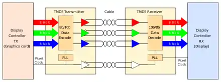
TMDS is similar to low-voltage differential signaling (LVDS) in that it uses differential signaling to reduce electromagnetic interference (EMI) which allows faster signal transfers with increased accuracy. TMDS also uses a twisted pair for noise reduction, rather than coaxial cable that is conventional for carrying video signals. Like LVDS, the data is transmitted serially over the data link. When transmitting video data and used in HDMI, three TMDS twisted pairs are used to transfer video data. Each of the three links corresponds to a different RGB component.
The physical layer for TMDS is current mode logic (CML),[2] DC coupled and terminated to 3.3 Volts. While the data is DC balanced (by the encoding algorithm), the DC coupling is part of the specification. TMDS can be switched or repeated by any method applicable to CML signals. However, if DC coupling to the transmitter is not preserved, some transmitters' "monitor detection" features may not work properly.
References
- Digital Visual Interface (PDF), Digital Display Working Group, 1999-04-02, archived (PDF) from the original on 2004-04-23
- DS34RT5110 DVI, HDMI Retimer with Input Equalization and Output De-Emphasis