Trace cache
In computer architecture, a trace cache or execution trace cache is a specialized instruction cache which stores the dynamic stream of instructions known as trace. It helps in increasing the instruction fetch bandwidth and decreasing power consumption (in the case of Intel Pentium 4) by storing traces of instructions that have already been fetched and decoded.[1] A trace processor[2] is an architecture designed around the trace cache and processes the instructions at trace level granularity. The formal mathematical theory of traces is described by trace monoids.

Background
The earliest academic publication of trace cache was "Trace Cache: a Low Latency Approach to High Bandwidth Instruction Fetching".[1] This widely acknowledged paper was presented by Eric Rotenberg, Steve Bennett, and Jim Smith at 1996 International Symposium on Microarchitecture (MICRO) conference. An earlier publication is US patent 5381533,[3] by Alex Peleg and Uri Weiser of Intel, "Dynamic flow instruction cache memory organized around trace segments independent of virtual address line", a continuation of an application filed in 1992, later abandoned.
Necessity
Wider superscalar processors demand multiple instructions to be fetched in a single cycle for higher performance. Instructions to be fetched are not always in contiguous memory locations (basic blocks) because of branch and jump instructions. So processors need additional logic and hardware support to fetch and align such instructions from non-contiguous basic blocks. If multiple branches are predicted as not-taken, then processors can fetch instructions from multiple contiguous basic blocks in a single cycle. However, if any of the branches is predicted as taken, then processor should fetch instructions from the taken path in that same cycle. This limits the fetch capability of a processor.

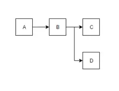
Consider these four basic blocks (A, B, C, D) as shown in the figure that correspond to a simple if-else loop. These blocks will be stored contiguously as ABCD in the memory. If the branch D is predicted not-taken, the fetch unit can fetch the basic blocks A, B, C which are placed contiguously. However, if D is predicted taken, the fetch unit has to fetch A,B,D which are non-contiguously placed. Hence, fetching these blocks which are non contiguously placed, in a single cycle will be very difficult. So, in situations like these trace cache comes in aid to the processor.
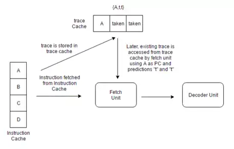
Once fetched, the trace cache stores the instructions in their dynamic sequence. When these instructions are encountered again, the trace cache allows the instruction fetch unit of a processor to fetch several basic blocks from it without having to worry about branches in the execution flow. Instructions will be stored in the trace cache either after they have been decoded, or as they are retired. However, instruction sequence is speculative if they are stored just after decode stage.
Trace structure
A trace, also called a dynamic instruction sequence, is an entry in the trace cache. It can be characterized by maximum number of instructions and maximum basic blocks. Traces can start at any dynamic instruction. Multiple traces can have same starting instruction i.e., same starting program counter (PC) and instructions from different basic blocks as per the branch outcomes. For the figure above, ABC and ABD are valid traces. They both start at the same PC (address of A) and have different basic blocks as per D's prediction.
Traces usually terminate when one of the following occurs:
- Trace got filled with allowable maximum number of instructions
- Trace has allowable maximum basic blocks
- Return instructions
- Indirect branches
- System calls
Trace control information
A single trace will have following information:
- Starting PC - PC of the first instruction in trace
- Branch flag - ( maximum basic blocks -1) branch predictions
- Branch mask - number of branches in the trace and whether trace ends in a branch or not
- Trace fall through - Next PC if last instruction is not-taken branch or not a branch
- Trace target - address of last branch's taken target
Trace cache design
Following are the factors that need to be considered while designing a trace cache.
- Trace selection policies - maximum number of instructions and maximum basic blocks in a trace
- Associativity - number of ways a cache can have
- Cache indexing method - concatenation or XOR with PC bits
- Path associativity - traces with same starting PC but with different basic blocks can be mapped to different sets
- Trace cache fill choices -
- After decode stage (speculative)
- After retire stage
A trace cache is not on the critical path of instruction fetch[4]
Hit/miss logic
Trace lines are stored in the trace cache based on the PC of the first instruction in the trace and a set of branch predictions. This allows for storing different trace paths that start on the same address, each representing different branch outcomes. This method of tagging helps to provide path associativity to the trace cache. Other method can include having only starting PC as tag in trace cache. In the instruction fetch stage of a pipeline, the current PC along with a set of branch predictions is checked in the trace cache for a hit. If there is a hit, a trace line is supplied to fetch unit which does not have to go to a regular cache or to memory for these instructions. The trace cache continues to feed the fetch unit until the trace line ends or until there is a misprediction in the pipeline. If there is a miss, a new trace starts to be built.
The Pentium 4's execution trace cache stores micro-operations resulting from decoding x86 instructions, providing also the functionality of a micro-operation cache. Having this, the next time an instruction is needed, it does not have to be decoded into micro-ops again.[5]
Disadvantages
The disadvantages of trace cache are:
- Redundant instruction storage between trace cache and instruction cache and within trace cache itself.[6]
- Power inefficiency and hardware complexity[4]
Execution trace cache
Within the L1 cache of the NetBurst CPUs, Intel incorporated its execution trace cache.[7][8] It stores decoded micro-operations, so that when executing a new instruction, instead of fetching and decoding the instruction again, the CPU directly accesses the decoded micro-ops from the trace cache, thereby saving considerable time. Moreover, the micro-ops are cached in their predicted path of execution, which means that when instructions are fetched by the CPU from the cache, they are already present in the correct order of execution. Intel later introduced a similar but simpler concept with Sandy Bridge called micro-operation cache (UOP cache).
References
- Rotenberg, Eric; Bennett, Steve; Smith, James E.; Rotenberg, Eric (1996-01-01). "Trace Cache: a Low Latency Approach to High Bandwidth Instruction Fetching". In Proceedings of the 29th International Symposium on Microarchitecture: 24–34.
- Eric Rotenberg, Quinn Jacobson, Yiannakis Sazeides, and James E. Smith. Trace Processors. Proceedings of the30th IEEE/ACM International Symposium on Microarchitecture (MICRO-30), pp. 138-148, December 1997
- Peleg, Alexander; Weiser, Uri (Jan 10, 1995), Dynamic flow instruction cache memory organized around trace segments independent of virtual address line, retrieved 2016-10-18
- Leon Gu; Dipti Motiani (October 2003). "Trace Cache" (PDF). Retrieved2013-10-06.
- Agner Fog (2014-02-19). "The microarchitecture of Intel, AMD and VIA CPUs: An optimization guide for assembly programmers and compiler makers" (PDF). agner.org. Retrieved 2014-03-21.
- Co, Michele. "Trace Cache". www.cs.virginia.edu. Retrieved 2016-10-21.
- https://pdfs.semanticscholar.org/presentation/cfcc/9d5a7480c4ea87e77084386d74aaff9a1ee1.pdf
- https://web.archive.org/web/20160306140603/http://www.xbitlabs.com/articles/cpu/print/replay.html