Taxiway
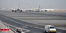
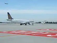
A taxiway is a path for aircraft at an airport connecting runways with aprons, hangars, terminals and other facilities. They mostly have a hard surface such as asphalt or concrete, although smaller general aviation airports sometimes use gravel or grass.


Most airports do not have a specific speed limit for taxiing (though some do). There is a general rule on safe speed based on obstacles. Operators and aircraft manufacturers might have limits. Typical taxi speeds are 20–30 knots (37–56 km/h; 23–35 mph).[1][2]
High-speed exit
Busy airports typically construct high-speed or rapid-exit taxiways to allow aircraft to leave the runway at higher speeds. This allows the aircraft to vacate the runway quicker, permitting another to land or take off in a shorter interval of time. This is usually accomplished by making the exiting taxiway longer, thus giving the aircraft more space in which to slow down, before the taxiways' upcoming intersection with another (perpendicular) taxiway, another runway, or the ramp/tarmac.
Markings

- Normal Centerline A single continuous yellow line, 15 centimetres (6 in) to 30 centimetres (12 in) in width.
- Enhanced Centerline The enhanced taxiway center line marking consists of a parallel line of yellow dashes on either side of the taxiway centerline. Taxiway centerlines are enhanced for 150 feet (46 m) before a runway holding position marking. The enhanced taxiway centerline is standard[3] at all FAR Part 139 certified airports in the USA.
- Taxiway Edge Markings Used to define the edge of the taxiway when the edge does not correspond with the edge of the pavement.
- Continuous markings consist of a continuous double yellow line, with each line being at least 15 centimetres (6 in) in width, spaced 15 centimetres (6 in) apart. They divide the taxiway edge from the shoulder or some other abutting paved surface not intended for use by aircraft.
- Dashed markings define the edge of a taxiway on a paved surface where the adjoining pavement to the taxiway edge is intended for use by aircraft, e.g. an apron. These markings consist of a broken double yellow line, with each line being at least 15 centimetres (6 in) in width, spaced 15 centimetres (6 in) apart (edge to edge). These lines are 15 feet (4.6 m) in length with 25 foot (7.6 m) gaps.
- Taxi Shoulder Markings Taxiways, holding bays, and aprons are sometimes provided with paved shoulders to prevent blast and water erosion. Shoulders are not intended for use by aircraft, and may be unable to carry the aircraft load. Taxiway shoulder markings are yellow lines perpendicular to the taxiway edge, from taxiway edge to pavement edge, about 3 metres.
- Surface Painted Taxiway Direction Signs Yellow background with a black inscription, provided when it is not possible to provide taxiway direction signs at intersections, or when necessary to supplement such signs. These markings are located on either side of the taxiway.
- Surface Painted Location Signs Black background with a yellow inscription and yellow and black border. Where necessary, these markings supplement location signs located alongside the taxiway and assist the pilot in confirming the designation of the taxiway on which the aircraft is located. These markings are located on the right side of the centerline.
- Geographic Position Markings These markings are located at points along low visibility taxi routes (when Runway visual range is below 1200 feet (370 m)). They are positioned to the left of the taxiway centerline in the direction of taxiing. Black inscription centered on pink circle with black inner and white outer ring. If the pavement is a light colour then the border is white with a black outer ring.

- Runway Holding Position Markings These show where an aircraft should stop when approaching a runway from a taxiway. They consist of four yellow lines, two solid and two dashed, spaced six or twelve inches (15 or 30 cm) apart, and extending across the width of the taxiway or runway. The solid lines are always on the side where the aircraft is to hold. There are three locations where runway holding position markings are encountered: Runway holding position markings on taxiways; runway holding position markings on runways; taxiways located in runway approach areas.
- Holding Position Markings for Instrument Landing System (ILS) These consist of two yellow solid lines spaced two feet (60 cm) apart connected by pairs of solid lines spaced ten feet (3 metres) apart extending across the width of the taxiway.
- Holding Position Markings for Taxiway/Taxiway Intersections These consist of a single dashed line extending across the width of the taxiway.
- Surface Painted Holding Position Signs Red background signs with a white inscription to supplement the signs located at the holding position.
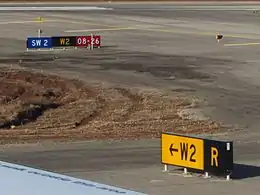
The taxiways are given alphanumeric identification. These taxiway IDs are shown on black and yellow signboards along the taxiways.
Signs
| Wikimedia Commons has media related to Airport signs. |

Airport guidance signs provide direction and information to taxiing aircraft and airport vehicles. Smaller airports may have few or no signs, relying instead on airport diagrams and charts.
There are two classes of signage at airports, with several types of each:
Operational guidance signs


- Location signs – yellow on black background. Identifies the runway or taxiway the aircraft is currently on or is entering.
- Direction/Runway exit signs – black on yellow. Identifies the intersecting taxiways the aircraft is approaching, with an arrow indicating the direction to turn.
- Stop Bar signs – white on blue background. The designation consists of the letter S followed by designation of the taxiway on which the Stop Bar is positioned. This sign is not standard.[4]
- Other – many airports use conventional traffic signs such as stop and yield signs throughout the airport.

Mandatory instruction signs

Mandatory instruction signs are white on red. They show entrances to runways or critical areas. Vehicles and aircraft are required to stop at these signs until the control tower gives clearance to proceed.
- Runway signs – White text on a red background. These signs identify a runway intersection ahead, e.g. runway 12-30 in the photo above.
- Frequency change signs – Usually a stop sign and an instruction to change to another frequency. These signs are used at airports with different areas of ground control.
- Holding position signs – A single solid yellow bar across a taxiway indicates a position where ground control may require a stop. If two solid yellow bars and two dashed yellow bars are encountered, this indicates a holding position for a runway intersection ahead; runway holding lines must never be crossed without permission. At some airports, a line of red lights across a taxiway is used during low visibility operations to indicate holding positions. An "interrupted ladder" type marking with an "ILS" sign in white on red indicates a holding position before an ILS critical area.
Lights

.jpg.webp)
.jpg.webp)
.jpg.webp)
For night operations, taxiways at many airports are equipped with lights, although some small airports are not equipped with them.
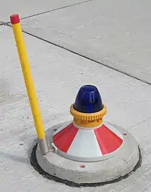
- Taxiway Edge Lights: used to outline the edges of taxiways during periods of darkness or restricted visibility conditions. These fixtures may be elevated or in-pavement and emit blue light normally. Where a four-way intersection crosses, the light at the centre of the crossing may be omnidirectional and emit yellow light. Where a road for ground vehicles only meets a taxiway or at an end of usable service area for a ramp or taxiway, the light at the edge of the road or the final taxiway edge light may emit red light.
- Taxiway Centerline Lights: They are steady burning and emit green light located along the taxiway centerline. Where a taxiway crosses a runway, or where a "lead-off" taxiway centreline leads off of a runway to join a taxiway, these lights will alternate yellow and green.
- Clearance Bar Lights: Three in-pavement steady-burning yellow lights installed at holding positions on taxiways
- Runway Guard Lights: Either a pair of elevated flashing yellow lights installed on either side of the taxiway, or a row of in-pavement yellow lights installed across the entire taxiway, at the runway holding position marking at taxiway/runway intersections.
- Stop Bar Lights: A row of red, unidirectional, steady-burning in-pavement lights installed across the entire taxiway at the runway holding position, and elevated steady-burning red lights on each side used in low visibility conditions (below 1,200 ft RVR). A controlled stop bar is operated in conjunction with the taxiway centerline lead-on lights which extend from the stop bar toward the runway. Following the ATC clearance to proceed, the stop bar is turned off and the lead-on lights are turned on.
Taxiway edge lights are spaced at a minimum of 50 to a maximum of 200 feet apart. On straightaways the spacing is typically 200 feet.
These lights can be closer together at taxiway intersections. On straight segments, Taxiway Centerline Lights are spaced at either 50 or 100 foot intervals depending on the minimum authorized visibility. On curved taxiway segments, Taxiway Centerline Lights may be required to be closer together.[5]
See also
References
- "Airplanes: At what speed do planes generally taxi?". February 9, 2016. Retrieved January 1, 2018.
- John Cox (November 23, 2014). "Ask the Captain: Making time on the taxiways". USA Today. Retrieved January 1, 2018.
- "FAA Advisory Circular No: 150/5340-1J March 31, 2008 – Standards for Airport Markings". Retrieved January 1, 2018. (canceled and replaced by150/5340-1K)
- "AIP Israel Amendment 2.5-1". December 16, 2010. Retrieved January 1, 2018. (LLBG AD 2.9 Surface Movement Guidance and Control System and Markings)
- , Page 2-7, Table 2-1.
External links
 Media related to Taxiways at Wikimedia Commons
- Sean Broderick (Feb 4, 2019). "TSB Canada Recommends Taxiway Changes At Toronto Pearson". Aviation Week Network.
https://www.faa.gov/documentLibrary/media/Advisory_Circular/150-5340-30J.pdf