Spinning mirror system
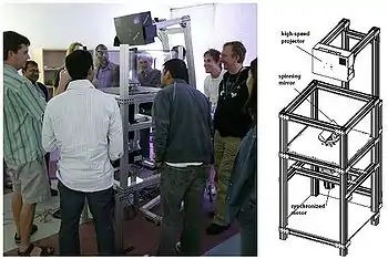
Spinning mirror systems are used to build interactive 3D graphics and autostereoscopic visuals visible to multiple simultaneous viewers, since a different view can be perceived by each viewer depending on the angle of vision.

Because these mirrors spin, they can reflect light from a projector to any outside point. Therefore, such systems can create omnidirectional projections. Because light is reflected directly from the projector to the audience and not projected onto a fixed plane, spinning mirror systems create a correct interpretation of the field of light regardless of a spectator's position relative to the system.
Because such systems are tied to a high speed video projector, the system's maximum resolution of unique angles is limited by the projector's maximum framerate.
A similar system was commercially released in 1981 for the Entex Adventure Vision game console. The console, however, didn't aim for 3D visualization, but instead used the spinning mirror to project a 2D picture from a row of LEDs.
Motivation
Previous volumetric systems projected the images in a diffuse plane of rotation, thus, the light was remaining dispersed in all directions. Unfortunately, these displays could not recreate dependent effects such as occlusion. This produced the need to create a system that was capable of settling misadventures as this one, but in turn, it had an easy implementation and was doing that his installation on systems was simple. Thus, create a system of gyratory mirrors covered by a holographic diffuser anisotropic.

Functioning
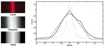
The mirrored surface reflects each projector pixel to a narrow range of viewpoints. The holographic diffuser provides control over the width and height of this region. The characteristics of the diffuser are such that the relative diffusion between x and y is approximately 1:200.
Horizontally, the surface is sharply specular to maintain a 1.25-degree separation between views. Vertically, the mirror scatters widely so the projected image can be viewed from essentially any height.
The horizontal profile of the specular lobe approximates a bilinear interpolation between adjacent viewpoints; the motion of the mirror adds some additional blur which improves the reproduction of halftoned imagery at the expense of angular resolution.
Montage
The anisotropic holographic diffuser and mirror assembly are mounted on a carbon fiber panel and attached to an aluminum flywheel at 45°. The flywheel spins synchronously relative to the images displayed by the projector.

Synchronization in a system
Because the output frame rate of the PC graphics card is relatively constant and cannot be fine-tuned on the fly, The PC video output rate is used as the master signal for system synchronization. The projector's FPGA also creates signals encoding the current frame rate. These control signals interface directly to an Animatics SM3420D ”Smart Motor” which contains firmware and motion control parameters resulting in a stable, velocity-based control loop that ensures the motor velocity stays in sync with the signals from the projector.
Projection of graphs on the screen

In this section we describe how to render a scene to the 3D display with correct perspective, using either scanline rendering or ray tracing. We assume that the spinning mirror is centered at the origin and that its axis of rotation is the vertical y-axis, with the video projector at the nodal point P above the mirror as in top figure. We further assume that the viewpoint for which the correct perspective should be obtained is at a height h and a distance d from the y axis.
By the rotational symmetry of our system, we can produce perspective-correct imagery for any viewing position on the circle V defined by h and d, yielding binocular images for a viewer facing the display since h and d will be similar for both eyes. We denote a particular viewpoint on the circle V as V’. In practice, the set of perspective-correct viewpoints V need not be a continuous planar circle and can pass through a variety of tracked viewer positions at different distances and heights.
Double spinning mirror system

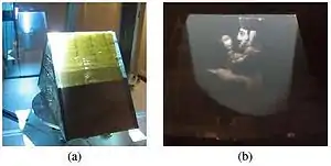
In advance of that, we have implemented a two-channel field-sequential color system using a two-sided tent-shaped diffusing mirror. For each side of the tent, we place a color filter between the holographic diffusing film and the first-surface mirror, which avoids introducing specular first-surface reflections. We chose a cyan filter for one side and an orange filter for the other, dividing the visible spectrum approximately evenly into short and long wavelengths.
We convert RGB colors to Orange-Cyan colors by projecting the linear RGB vector onto the plane spanned by the Orange and Cyan colors.
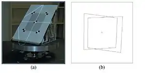
To render in color, we calibrate each plane of the tent mirror independently as in Section 5. Then, we render the 3D scene twice for each sub-frame, once for the orange side and once for the cyan side, and the calibration process ensures that each side is rendered toward the appropriate set of viewpoints. The effect for the viewer is similar to the Kinemacolor, 2-color cinema system and the choice of filters allows for useful color reproduction for many scenes.
Applications
- System Maeda [Maeda, 2003]: it is based on a system of a monitor of gyratory LCD. The weight of this monitor limits the rate of update, allowing only five revolutions per second, obtaining only five independent points of view.
- System Transport [Otsuka, 2006]: it realizes 24 images in the foreign edge of the projected video and reflects these images on a screen anisotropic of rapid rotation using a circle created by different faces of mirrors.
- 3D Videoconference [California, 2009]: It is based on a structure composed of two mirrors on those who reflect the images and create different perspectives about his 360 degrees.
Articles and books
- TRAVIS, A. R. L. 1997. The display of three-dimensional video images.
- ENDO, T., KAJIKI, Y., HONDA, T., AND SATO, M. 2000. Cylindrical 3D video display observable from all directions.
- DODGSON, N. A. 2005. Autostereoscopic 3D displays.
- MCDOWALL, I., AND BOLAS, M. 2005. Display, sensing, and control applications for digital micromirror displays.
- FAVALORA, G. E. 2005. Volumetric 3D displays and application infrastructure.
- OTSUKA, R., HOSHINO, T., AND HORRY, Y. 2006. Transpost: A novel approach to the display and transmission of 360 degreesviewable 3D solid images.
- AGOCS, T., BALOGH, T., FORGACS, T., BETTIO, F., GOBBETTI, E., ZANETTI, G., AND BOUVIER, E. 2006. A large scale interactive holographic display.
External links
• Video depicting a spinning mirror system
• Type of Display obtained thanks to the described technology
• Article about the use of the system in 3D Teleconferencing