Molex connector
Molex connector is the vernacular term for a two-piece pin and socket interconnection. Pioneered by Molex Connector Company, the two-piece design became an early electronic standard. Molex developed and patented the first examples of this connector style in the late 1950s and early 1960s.[1][2] First used in home appliances, other industries soon began designing it into their products from automobiles to vending machines to mini-computers.

In such a connector, cylindrical spring-metal pins fit into cylindrical spring-metal sockets. The pins and sockets are held in a rectangular matrix in a nylon shell. The connector typically has 2 to 24 contacts and is polarized or keyed to ensure correct orientation. Pins and sockets can be arranged in any combination in a single housing, and each housing can be either male or female.
There are three typical pin sizes: 1.57 mm (0.062 in), 2.13 mm (0.084 in), and 2.36 mm (0.093 in). The 1.57 mm pin can carry 5 A of current, while the 2.36 mm can carry 8.5 A. Because the pins have a large contact surface area and fit tightly, these connectors are typically used for power.


In October 1963, AMP (now TE Connectivity) introduced the Mate-n-Lok connector.[3] The AMP connector was similar to the patented Molex connectors but not interchangeable. Both were widely used in the computer industry and the term "Molex connector" is often inaccurately used to refer to all nylon plugs and receptacles.
The first 5.25-inch floppy disk drive, the Shugart SA400, introduced in August 1976, used the AMP Mate-n-Lok connector part number 350211-1.[4] This connector became the standard for 5.25-inch format peripherals such as hard drives and was used until introduction of SATA drives. In 1983, Molex introduced the 8981 connector under the trademark Disk Drive Power Connection System,[5] which was fully compatible with the AMP Mate-n-Lok connector.[6] The Molex 8981 series was only produced in a 4 position option, unlike the Mate-n-Lok family which includes many other contact arrangements.
Desktop PC use
Several connector types have become established for connecting power in desktop PCs because of the simplicity, reliability, flexibility, and low cost of the Molex design. Certain Molex connectors are used for providing power to the motherboard, fans, floppy disk drive, CD/DVD drive, video card, some older hard drive models, and more. Compatible connectors are available from many manufacturers, not just Molex and AMP.
Motherboard
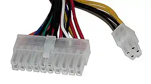
ATX motherboard power connector (Molex Mini-fit Jr. 39-28-1203,[7] former 5566-20A or 39-28-1243,[8] former 5566-24A)

In 20/24-pin configurations, the Mini-Fit Jr. connector may be used on ATX motherboards as the main power connector. The same style of connector, in single or paired 4-, 6-, or 8-pin configurations, may be used for additional CPU power and graphics card power. Power delivery to these devices has increased in successive generations of PC components, as their higher signal sophistication and speed requirements have raised their electrical demands. The Mini-Fit Jr. can also be found in other consumer and industrial electric devices, such as major appliances, with high circuit density and high current requirements.
These connectors are polarized so that they usually cannot be inserted incorrectly. They lock into position using an integrated latch.
Standard pinout:
| Color | Signal[upper-alpha 1] | Pin[upper-alpha 2] | Pin[upper-alpha 2][upper-alpha 3] | Signal[upper-alpha 1] | Color |
|---|---|---|---|---|---|
| Orange | +3.3 V | 1 | 13 | +3.3 V | Orange |
| +3.3 V sense[upper-alpha 4] | Brown | ||||
| Orange | +3.3 V | 2 | 14 | −12 V | Blue |
| Black | Ground | 3 | 15 | Ground | Black |
| Red | +5 V | 4 | 16 | Power on[upper-alpha 5] | Green |
| Black | Ground | 5 | 17 | Ground | Black |
| Red | +5 V | 6 | 18 | Ground | Black |
| Black | Ground | 7 | 19 | Ground | Black |
| Grey | Power good[upper-alpha 6] | 8 | 20 | Reserved[upper-alpha 7] | None |
| Purple | +5 V standby | 9 | 21 | +5 V | Red |
| Yellow | +12 V | 10 | 22 | +5 V | Red |
| Yellow | +12 V | 11 | 23 | +5 V | Red |
| Orange | +3.3 V | 12 | 24 | Ground | Black |
| |||||
Power good goes high to indicate that voltages are stabilised and ready for use. Power on is internally driven high, and shorting this pin to ground will turn on the power supply.
AT motherboard power connector (P8 & P9 connector, Molex 90331)
Older, AT motherboards utilized two connectors, commonly referred to as "P8" and "P9" that were positioned directly next to each other. These supplied +5V, +12V, −5V, −12V, "power-good signal", and ground. The most notable difference from modern 20/24-pin ATX power connectors is that the AT power supply connector did not have a signal to turn on the power supply, and also did not supply separate, "always-on" +5V standby power. The power supply was instead turned on and off via a heavy mechanical switch which removed mains power. Modern, ATX supplies, by contrast, are capable of being switched on and off by the computer itself, and the power button is actually a signal that is received by the motherboard and in turn passed along to the power supply. This allows the motherboard to remove power upon shutdown (with the exception of the aforementioned 5V standby power, which is always on), and also to "wake up" the computer by events such as key presses, mouse clicks, "wake on lan" events, and scheduled alarm times. These "wakeup" features are often configurable via the BIOS/CMOS setup.
Disk drive
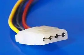
Disk drive connector (AMP Mate-n-Lok 1-480424-0 power connector)
 AMP Mate-n-Lok 1-480424-0 Power connector (female pins, male connector) | |||
| Type | Electrical power connector | ||
|---|---|---|---|
| Production history | |||
| Manufacturer | AMP | ||
| Produced | 1963 | ||
| General specifications | |||
| Width | 21 mm (female), 23 mm (male) | ||
| Height | 6 mm (female), 8 mm (male) | ||
| Pins | 4 | ||
| Electrical | |||
| Signal | Yes | ||
| Max. voltage | 12 V | ||
| Max. current | 11 A/pin (18AWG w/30 °C rise) | ||
| Pin out | |||
 | |||
| Male pins (female connector) | |||
| Pin | Color | Type | |
| Pin 1 | Yellow | +12 V | |
| Pin 2 | Black | Ground | |
| Pin 3 | Black | Ground | |
| Pin 4 | Red | +5 V | |
| 18 AWG wire is typically used. | |||
The desktop computer hard-drive connector is pictured here. It has four conductors, with the standard pinout as follows:
| Pin # | Color | Function | |
|---|---|---|---|
| 1 | Yellow | +12 V | |
| 2 | Black | Ground | |
| 3 | Black | Ground | |
| 4 | Red | +5 V | |
Sometimes, especially in older computers, the colors differ. The pins are 0.200 in (5.08 mm) apart (center to center). The connector housing has chamfered corners on one side to prevent the user from plugging it in incorrectly. The connector that provides power (e.g., on a power supply) has female pins and a male housing; the connector that receives power (e.g., on a peripheral) has male pins and a female housing.
The connector is standard on all 5.25-inch floppy drives, 3.5-inch PATA and non-SCA SCSI disk drives; however, newer SATA disk drives employ a more advanced interconnection with 15 contacts. These advanced connection systems were first developed by Molex and other connector companies, often working together to develop interconnection standards. As SATA becomes more prevalent, Molex connectors can be found repurposed, through use of an adaptor, to serve as six-pin PCIe power connectors to make up for a lack of such connectors on a power supply.
Lower power devices (e.g. 3.5-inch floppy drives) use the smaller AMP 171822-4 connector instead.
Despite its widespread adoption, the connector does have problems. It is difficult to remove because it is held in place by friction instead of a latch, and some poorly constructed connectors may have one or more pins detach from the connector during mating or de-mating. There is also a tendency for the loosely inserted pins on the male connector to skew out of alignment. The female sockets can spread, making the connection imperfect and subject to arcing. Standard practice is to check for any sign of blackening or browning on the white plastic shell, which would indicate the need to replace the arcing connector. In extreme cases the whole connector can melt due to the heat from arcing.
References
- Krehbiel, John H.; "Wire Connector" US 3178673, issued April 1965
- Krehbiel, John H.; "Electrical Connector Having Resilient Accurately Bendable Locking Means", US 3409858, issued November 1968
- United States Patent and Trademark Office, Word Mark MATE-N-LOK for Electrical Connectors first used in commerce Oct 18, 1963, Serial Number 72179683, Filing Date October 24, 1963, Registration Number 0786321, Registration Date March 9, 1965, Owner AMP Incorporated
- SA400 Minifloppy Diskette Storage Drive, OEM Manual (PDF). Shugart Associates. 1977. p. 18 – via BitSavers.Trailing-Edge.com.
- "Molex Connector Part Number - 15244048". www.molex.com.
- "Power plug serves disk drives". Electronic Design. Hayden Publishing Company. 31 (22). October 27, 1983.
A four-circuit power plug, the 8981 header, is intended primarily for computer disk drives.
- "Molex Connector Part Number - 39-28-1203". www.molex.com.
- "Molex Connector Part Number - 39-28-1243". www.molex.com.
- "ATX Specification Version 2.1" (PDF). Archived from the original (PDF) on 2003-09-24.
External links
| Wikimedia Commons has media related to Molex_Connectors. |