Jet mill
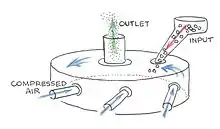
A jet mill grinds materials by using a high speed jet of compressed air or inert gas to impact particles into each other.[1] Jet mills can be designed to output particles below a certain size while continuing to mill particles above that size, resulting in a narrow size distribution of the resulting product.[2] Particles leaving the mill can be separated from the gas stream by cyclonic separation.[3]

Particle size
A jet mill consists of a short cylinder, meaning the cylinder's height is less than its diameter. Compressed gas is forced into the mill through nozzles tangent to the cylinder wall, creating a vortex. The gas leaves the mill through a tube along the axis of the cylinder. Solid particles in the mill are subject to two competing forces:
- Centrifugal force created by the particles traveling in circles
- Centripetal force created by the drag from the gas as it flows from the nozzles along the wall to the outlet in the center of the mill

Fd points toward the center of the mill, and Fg points to the wall.
The drag on small particles is less than large particles, according to the formula derived from Stokes' law,
- ,
where V is the flow settling velocity (m/s) (vertically downwards if ρp > ρf, upwards if ρp < ρf ), g is the gravitational acceleration (m/s2), ρp is the mass density of the particles (kg/m3), ρf is the mass density of the fluid (kg/m3), μ is the dynamic viscosity (kg /m*s), and R is the radius of the spherical particle (m).
The formula shows that particles will be pulled toward the wall of the mill according to the square of their radius or diameter. Large particles will continue the comminution process, until they are small enough to stay in the center of the mill where the discharge port is located.
Typical parameters
- Diameter of mill: from 0.05 meters to 1 meter (from 2 inches to 42 inches)
- Gas pressure: 8.3 Bar (120 PSI)
- Starting particle size: 800 microns or less, or as limited by the size of the inlet of the feed venturi
- Final particle size: down to 0.5 microns
References
- Mohamed Rahaman; Mohamed N. Rahaman (7 August 2006). Ceramic Processing. CRC Press. pp. 41–. ISBN 978-0-8493-7285-8.
- John B. Wachtman (28 September 2009). Materials and Equipment - Whitewares Manufacturing: Ceramic Engineering and Science Proceedings, Volume 14. John Wiley & Sons. pp. 264–. ISBN 978-0-470-31618-4.
- Oleg D Neikov; I. B. Murashova; Nicholas A. Yefimov; Stanislav Naboychenko (24 February 2009). Handbook of Non-Ferrous Metal Powders: Technologies and Applications. Elsevier. pp. 60–. ISBN 978-0-08-055940-7.