Differential steering
Differential steering is the means of steering a land vehicle by applying more drive torque to one side of the vehicle than the other.[1] Differential steering is the primary means of steering tracked vehicles, such as tanks and bulldozers, is also used in certain wheeled vehicles commonly known as skid-steer, and even implemented in some automobiles, where it is called torque vectoring, to augment steering by changing wheel direction relative to the vehicle. Differential steering is distinct from torque steer, which is usually considered a negative side effect of drive-train design choices.

History

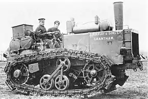
A British agricultural company, Hornsby in Grantham, developed a continuous track, which was patented in 1905.[2] The Hornsby tractors featured a track-steer clutch arrangement.
Mechanisms
There are several mechanisms that have been developed to vary the torque applied to different sides of a vehicle. These include clutch-brake steering, braked-differential steering, controlled-differential steering, geared steering, Maybach double-differential steering, double-differential steering, triple-differential steering,[1] hydraulic,[3] and electric.
Clutch-brake
In clutch-brake differential steering, power is disconnected to one side or the other with a clutch, and the unpowered side may also have a brake applied to tighten the turn.[1] Note that there is no differential gearset in this design. The tracks on either side of the vehicle will always turn at the same speed unless one is declutched for steering. This method is simple to implement but inefficient and only suitable for light vehicles. Also, when traveling downslope under engine braking, declutching one side to turn can result in a turn in the other direction.[1][4]

Braked-differential
In brake-differential steering, power is applied to both sides through a differential and a brake is applied to one side or the other. The slowing of one side causes the other side to speed up, because of the differential, and so the vehicle maintains a constant speed. A subsequent disadvantage is that changes in rolling resistance or traction from one side to the other automatically causes the vehicle to steer unless counteracted by the driver.[1] Differential steering of this type was used in many half-track designs to assist with making tight turns.
Controlled-differential
In controlled-differential steering, pinions within the differential are locked causing one side to rotate faster than the other. An advantage is that no power is lost to braking. A disadvantage is that only one turning radius can be performed efficiently. This method was developed by the Cleveland Tractor Company in 1921 and called the Cletrac Regenerative Steering System.[1]
Geared
In geared differential steering, two complete gearboxes are used to provide power to either side, and one distinct turning radius can be derived from each gear ratio combination. The main disadvantage to this system is that it doubles the size and weight of the total transmission and therefore it has only been implemented experimentally.[1]
Maybach double-differential
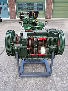
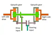
In the Maybach double-differential, power is transmitted through a single main transmission and then through an epicycle gear final drive on each side. A different drive speed is caused by feeding torque, from a separate "steering" transmission, into one final drive or the other using a pair of clutches. Usually the steering input turns at a fixed ratio relative to the engine, which results in a different turn radius for each main transmission ratio. This system was implemented on German Panther tanks during World War II.[1] The drawback of this design compared to other multiple-differential designs is that applying the steering input to one track also increases the average speed of the two tracks, so the vehicle's speed is not constant.
Double-differential

In double-differential steering, as in the Maybach double-differential system, power from a second transmission is fed an epicycle gear in the final drive of one side or the other. In this design, however, the average drive speed of the tracks is maintained by adding an idler to apply the opposite torque to the epicycle gear on other side of the turn. A pair of clutches is used to apply the steering transmission output, which only turns one direction, to the steering cross-shaft in either direction. This system was developed in 1928 by Major Wilson.[1] Here, the steering input is used not so much to apply torque to either side but rather to control the difference in torque and speed between the two sides.
Also note that, in any of the double- or triple-differential steering methods, the efficient turn radii (e.g., with no steering clutch or brake slipping) are determined by the ratio between the steering input speed and the main drive input speed into each epicyclic final drive. This means that having multiple ratios in the steering transmission results in multiple turn radii for each main drive transmission ratio. The additional complexity in the mechanical systems and driving controls means that this capability is rarely implemented.
Triple-differential
Triple-differential steering is similar to double-differential steering except that, rather than using a steering cross-shaft and an idler gear, it uses two steering cross-shafts connected to a steering differential. Part of the drive torque is always applied through the steering differential and the two epicyclic differentials. Brakes are used, instead of clutches, to slow down one or the other steering cross-shaft. The steering works much like braked differential steering mentioned above except that the resulting inefficiency from applying the steering brakes only affects the torque being transmitted via the steering input.
Hydraulic
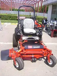
Hydraulic differential steering consists of a hydraulic drive system with one hydraulic pump and two hydraulic motors, one for each side.[3] This system is often employed on skid-steer loaders and zero-turn mowers.
Electric

Electric differential steering consists of two electric motors, one for each side, that are driven at different speeds, depending on steering needs. It is often implemented in wheeled robots.
Hand
Most traditional wheelchairs are maneuvered by differential steering when propelled by the occupant.
Turning radius
Depending on implementation, friction between drive mechanism and ground, and available power, a vehicle with differential steering may have a zero turning radius or a curb-to-curb turning circle equal to the length of the vehicle by driving each side at the same speed but in opposite directions. This is also called a neutral turn.[5] Vehicles on which only one drive wheel on each side is rigidly aligned and all others are free to caster, such as wheelchairs and wheeled robots, require the least power to turn. Vehicles with long continuous tracks on each side which must slide on the ground in order to turn at all require more power.
Examples


- Tanks, armored personnel carriers, armoured vehicle-launched bridge, self-propelled anti-aircraft weapon, and similar military vehicles
- Bulldozers, excavators, tractors, snowcats, trenchers, and other heavy equipment
- Skid-steer loaders and their derivatives
- Amphibious ATVs
- Zero-turn mowers
- Differential wheeled robots
- Wheel chairs
See also
References
- Phillip Edwards (September 1988). "Differentials, the Theory and Practice". Constructor Quarterly. Retrieved 2017-11-13.
- British Patent No. 16,345 (1904)
- Karim Nice. "How Caterpillar Skid Steer Loaders & Multi Terrain Loaders Work". How Stuff Works. Retrieved 2017-11-23.
- Stuart J. McGuigan; Peter J. Moss (November 1998). "A Review of Transmission Systems for Tracked Military Vehicles". Journal of Battlefield Technology. 1 (3). Retrieved 2017-11-23.
- Michael Green; James D. Brown (2008). Tiger Tanks at War. MBI Publishing Company. p. 46. ISBN 9781610600316.