Crusher
A crusher is a machine designed to reduce large rocks into smaller rocks, gravel, sand or rock dust.
Crushers may be used to reduce the size, or change the form, of waste materials so they can be more easily disposed of or recycled, or to reduce the size of a solid mix of raw materials (as in rock ore), so that pieces of different composition can be differentiated. Crushing is the process of transferring a force amplified by mechanical advantage through a material made of molecules that bond together more strongly, and resist deformation more, than those in the material being crushed do. Crushing devices hold material between two parallel or tangent solid surfaces, and apply sufficient force to bring the surfaces together to generate enough energy within the material being crushed so that its molecules separate from (fracturing), or change alignment in relation to (deformation), each other. The earliest crushers were hand-held stones, where the weight of the stone provided a boost to muscle power, used against a stone anvil. Querns and mortars are types of these crushing devices.
Background history
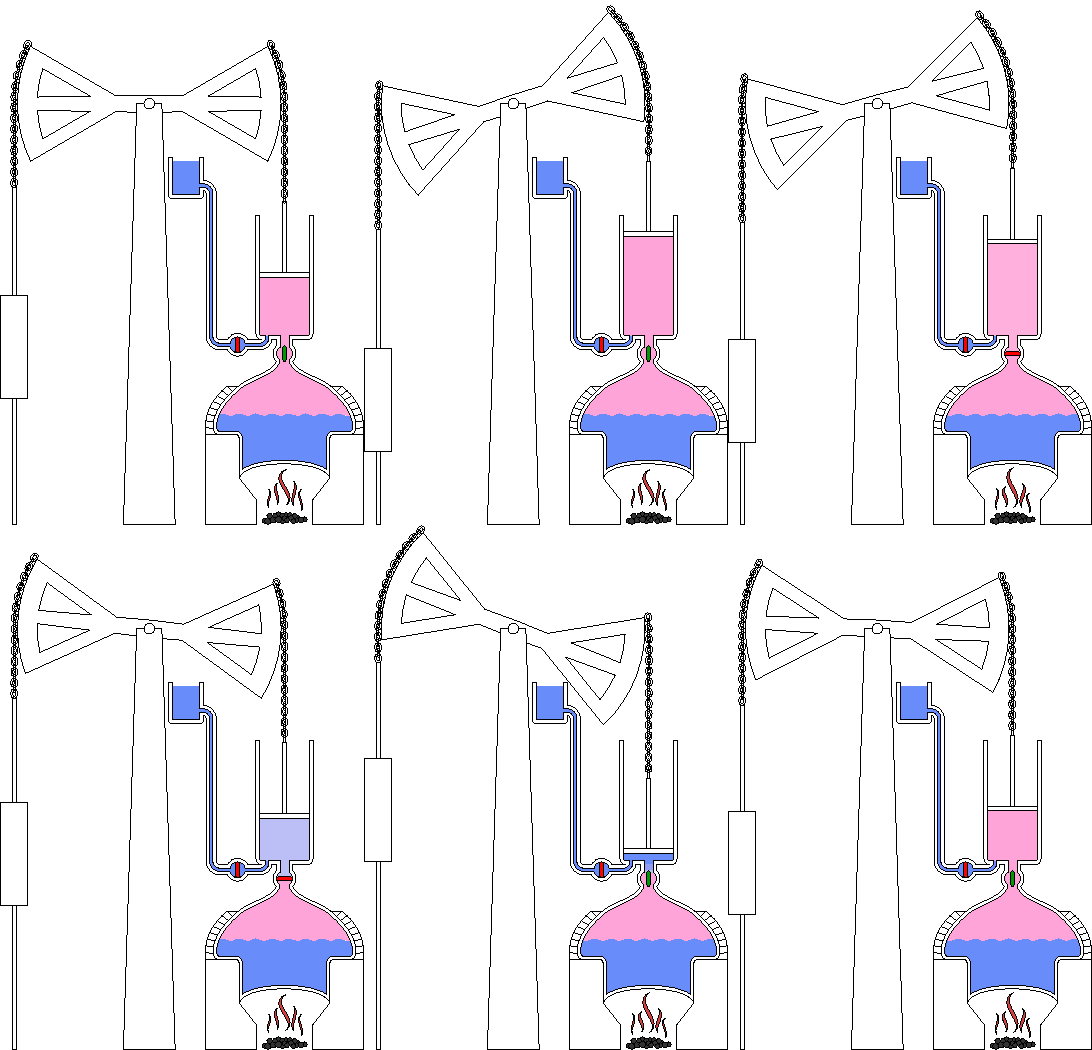
– Steam is shown pink and water is blue.
– Valves move from open (green) to closed (red)
The atmospheric engine invented by Thomas Newcomen in 1712, often referred to simply as a Newcomen engine, was the first practical device to harness the power of steam to produce mechanical work.[1] Newcomen engines were used throughout Britain and Europe, principally to pump water out of mines, starting in the early 18th century. James Watt's later Watt steam engine was an improved version of the Newcomen engine. As a result, Watt is today better known than Newcomen in relation to the origin of the steam engine.
In industry, crushers are machines which use a metal surface to break or compress materials into small fractional chunks or denser masses. Throughout most of industrial history, the greater part of crushing and mining part of the process occurred under muscle power as the application of force concentrated in the tip of the miners pick or sledge hammer driven drill bit. Before explosives came into widespread use in bulk mining in the mid-nineteenth century, most initial ore crushing and sizing was by hand and hammers at the mine or by water powered trip hammers in the small charcoal fired smithies and iron works typical of the Renaissance through the early-to-middle industrial revolution. It was only after explosives, and later early powerful steam shovels produced large chunks of materials, chunks originally reduced by hammering in the mine before being loaded into sacks for a trip to the surface, chunks that were eventually also to lead to rails and mine railways transporting bulk aggregations that post-mine face crushing became widely necessary. The earliest of these were in the foundries, but as coal took hold the larger operations became the coal breakers that fueled industrial growth from the first decade of the 1600s to the replacement of breakers in the 1970s through the fuel needs of the present day. The gradual coming of that era and displacement of the cottage industry based economies was itself accelerated first by the utility of wrought and cast iron as a desired materials giving impetus to larger operations, then in the late-sixteenth century by the increasing scarcity of wood lands for charcoal production to make the newfangled window glass[2] material that had become—along with the chimney— 'all the rage' among the growing middle-class and affluence of the sixteenth-and-seventeenth centuries;and as always, the charcoal needed to smelt metals, especially to produce ever larger amounts of brass and bronze,[3] pig iron, cast iron and wrought iron demanded by the new consumer classes. Other metallurgical developments such as silver and gold mining mirrored the practices and developments of the bulk material handling methods and technologies feeding the burgeoning appetite for more and more iron and glass, both of which were rare in personal possessions until the 1700s.
Things only became worse when the English figured out how to cast the more economical iron cannons (1547), following on their feat of becoming the armorers of the European continent's powers by having been leading producers brass and bronze guns,[3] and eventually by various acts of Parliament, gradually banned or restricted the further cutting of trees for charcoal in larger and larger regions in the United Kingdom.[2] In 1611, a consortium led by courtier Edward Zouch was granted a patent for the reverberatory furnace, a furnace using coal, not precious national timber reserves,[4] which was immediately employed in glass making. An early politically connected and wealthy Robber Baron figure Sir Robert Mansell bought his way into the fledgling furnace company wrested control of it, and by 1615 managed to have James I issued a proclamation forbidding the use of wood to produce glass,[4] giving his families extensive coal holdings a monopoly on both source and means of production for nearly half-a-century. Abraham Darby a century later relocated to Bristol where he had established a building brass and bronze industry by importing Dutch workers and using them to raid Dutch techniques. Both materials were considered superior to iron for cannon, and machines as they were better understood. But Darby would change the world in several key ways.
Where the Dutch had failed in casting iron, one of Darby's apprentices, John Thomas succeeded in 1707[5] and as Burke put it: "had given England the key to the Industrial Revolution"[5]. At the time, mines and foundries were virtually all small enterprises except for the tin mines (driven by the price and utility of brass) and materials came out of the mines already hammered small by legions of miners who had to stuff their work into carry sacks for pack animal slinging. Concurrently, mines needed drained resulting in Savery and Newcomen's early steam driven pumping systems. The deeper the mines went, the larger the demand became for better pumps, the greater the demand for iron, the greater the need for coal, the greater the demand for each. Seeing ahead clearly, Darby, sold off his brass business interests and relocated to Coalbrookdale with its plentiful coal mines, water power and nearby ore supplies. Over that decade his foundries developed iron casting technologies and began to supplant other metals in many applications. He adapted Coking of his fuel by copying Brewers practices.[5] In 1822 the pumping industries needs for larger cylinders met up with Darby's ability to melt sufficient quantities of pig iron to cast large inexpensive iron cylinders instead of costly brass ones,[5] reducing the cost of cylinders by nine-tenths.[6]
With gunpowder being increasingly applied to mining, rock chunks from a mining face became much larger, and the blast dependent mining itself had become dependent upon an organized group, not just an individual swinging a pick. Economies of scale gradually infused industrial enterprises, while transport became a key bottleneck as the volume of moved materials continued to increase following demand. This spurred numerous canal projects, inspired laying first wooden, then iron protected rails using draft animals to pull loads in the emerging bulk goods transportation dependent economy. In the coal industry, which grew up hand in hand as the preferred fuel for smelting ores, crushing and preparation (cleaning) was performed for over a hundred years in coal breakers, massive noisy buildings full of conveyors, belt-powered trip-hammer crushing stages and giant metal grading/sorting grates. Like mine pumps, the internal conveyors and trip-hammers contained within these 7—11 story buildings.
Industrial use
Mining operations use crushers, commonly classified by the degree to which they fragment the starting material, with primary and secondary crushers handling coarse materials, and tertiary and quaternary crushers reducing ore particles to finer gradations. Each crusher is designed to work with a certain maximum size of raw material, and often delivers its output to a screening machine which sorts and directs the product for further processing. Typically, crushing stages are followed by milling stages if the materials need to be further reduced. Additionally rockbreakers are typically located next to a crusher to reduce oversize material too large for a crusher. Crushers are used to reduce particle size enough so that the material can be processed into finer particles in a grinder. A typical processing line at a mine might consist of a crusher followed by a SAG mill followed by a ball mill. In this context, the SAG mill and ball mill are considered grinders rather than crushers.
In operation, the raw material (of various sizes) is usually delivered to the primary crusher's hopper by dump trucks, excavators or wheeled front-end loaders. A feeder device such as an apron feeder, conveyor or vibrating grid controls the rate at which this material enters the crusher, and often contains a preliminary screening device which allows smaller material to bypass the crusher itself, thus improving efficiency. Primary crushing reduces the large pieces to a size which can be handled by the downstream machinery.
Some crushers are mobile and can crush rocks as large as 1.5 meter (60 inches). Primarily used in-pit at the mine face these units are able to move with the large infeed machines (mainly shovels) to increase the tonnage produced. In a mobile road operation, these crushed rocks are directly combined with concrete and asphalt which are then deposited on to a road surface. This removes the need for hauling oversized material to a stationary crusher and then back to the road surface.
Types of crushers

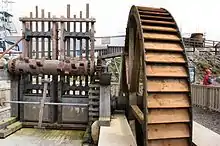 Cornish stamps used in the 19th century for breaking tin ore
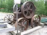 A portable rock crusher from the early 20th century
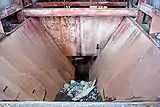 The entrance bin of a mine rock crusher
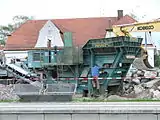 Mobile crusher
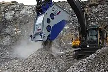 Crusher bucket in a quarry
The following table describes typical uses of commonly used crushers:
| Type | Hardness | Abrasion limit | Moisture content | Reduction ratio | Main use |
|---|---|---|---|---|---|
| Jaw crushers | Soft to very hard | No limit | Dry to slightly wet, not sticky | 3/1 to 5/1 | Heavy mining, quarried materials, sand & gravel, recycling |
| Gyratory crushers | Soft to very hard | Abrasive | Dry to slightly wet, not sticky | 4/1 to 7/1 | Heavy mining, quarried materials |
| Cone crushers | Medium hard to very hard | Abrasive | Dry or wet, not sticky | 3/1 to 5/1 | Quarried materials, sand & gravel |
| Compound crusher | Medium hard to very hard | Abrasive | Dry or wet, not sticky | 3/1 to 5/1 | Mine, building materials |
| Horizontal shaft impactors | Soft to medium hard | Slightly abrasive | Dry or wet, not sticky | 10/1 to 25/1 | Quarried materials, sand & gravel, recycling |
| Vertical shaft impactors (shoe and anvil) | Medium hard to very hard | Slightly abrasive | Dry or wet, not sticky | 6/1 to 8/1 | Sand & gravel, recycling |
| Vertical shaft impactors (autogenous) | Soft to very hard | No limit | Dry or wet, not sticky | 2/1 to 5/1 | Quarried materials, sand & gravel |
| Mineral sizers | Hard to soft | Abrasive | Dry or wet and sticky | 2/1 to 5/1 | Heavy mining |
| Crusher buckets | Soft to very hard | No limit | Dry or wet and sticky | 3/1 to 5/1 | Heavy mining, quarried materials, sand & gravel, recycling |
Jaw crusher
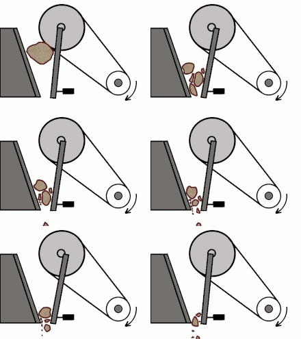

A jaw crusher uses compressive force for breaking of particle. This mechanical pressure is achieved by the two jaws of the crusher of which one is fixed while the other reciprocates. A jaw or toggle crusher consists of a set of vertical jaws, one jaw is kept stationary and is called a fixed jaw while the other jaw called a swing jaw, moves back and forth relative to it, by a cam or pitman mechanism, acting like a class II lever or a nutcracker. The volume or cavity between the two jaws is called the crushing chamber. The movement of the swing jaw can be quite small, since complete crushing is not performed in one stroke. The inertia required to crush the material is provided by a flywheel that moves a shaft creating an eccentric motion that causes the closing of the gap.
Jaw crushers are heavy duty machines and hence need to be robustly constructed. The outer frame is generally made of cast iron or steel. The jaws themselves are usually constructed from cast steel. They are fitted with replaceable liners which are made of manganese steel, or Ni-hard (a Ni-Cr alloyed cast iron). Jaw crushers are usually constructed in sections to ease the process transportation if they are to be taken underground for carrying out the operations.
Jaw crushers are classified on the basis of the position of the pivoting of the swing jaw
- Blake crusher-the swing jaw is fixed at the lower position
- Dodge crusher-the swing jaw is fixed at the upper position
- Universal crusher-the swing jaw is fixed at an intermediate position
The Blake crusher was patented by Eli Whitney Blake in 1858. The Blake type jaw crusher has a fixed feed area and a variable discharge area. Blake crushers are of two types- single toggle and double toggle jaw crushers.
In the single toggle jaw crushers, the swing jaw is suspended on the eccentric shaft which leads to a much more compact design than that of the double toggle jaw crusher. The swing jaw, suspended on the eccentric, undergoes two types of motion- swing motion towards the fixed jaw due to the action of toggle plate and vertical movement due to the rotation of the eccentric. These two motions, when combined, lead to an elliptical jaw motion. This motion is useful as it assists in pushing the particles through the crushing chamber. This phenomenon leads to higher capacity of the single toggle jaw crushers but it also results in higher wear of the crushing jaws. These type of jaw crushers are preferred for the crushing of softer particles.
In the double toggle jaw crushers, the oscillating motion of the swing jaw is caused by the vertical motion of the pitman. The pitman moves up and down. The swing jaw closes, i.e., it moves towards the fixed jaw when the pitman moves upward and opens during the downward motion of the pitman. This type is commonly used in mines due to its ability to crush tough and abrasive materials.
In the Dodge type jaw crushers, the jaws are farther apart at the top than at the bottom, forming a tapered chute so that the material is crushed progressively smaller and smaller as it travels downward until it is small enough to escape from the bottom opening. The Dodge jaw crusher has a variable feed area and a fixed discharge area which leads to choking of the crusher and hence is used only for laboratory purposes and not for heavy duty operations.
Gyratory crusher
.jpg.webp)
A gyratory crusher is similar in basic concept to a jaw crusher, consisting of a concave surface and a conical head; both surfaces are typically lined with manganese steel surfaces. The inner cone has a slight circular movement, but does not rotate; the movement is generated by an eccentric arrangement. As with the jaw crusher, material travels downward between the two surfaces being progressively crushed until it is small enough to fall out through the gap between the two surfaces.
A gyratory crusher is one of the main types of primary crushers in a mine or ore processing plant. Gyratory crushers are designated in size either by the gape and mantle diameter or by the size of the receiving opening. Gyratory crushers can be used for primary or secondary crushing. The crushing action is caused by the closing of the gap between the mantle line (movable) mounted on the central vertical spindle and the concave liners (fixed) mounted on the main frame of the crusher. The gap is opened and closed by an eccentric on the bottom of the spindle that causes the central vertical spindle to gyrate. The vertical spindle is free to rotate around its own axis. The crusher illustrated is a short-shaft suspended spindle type, meaning that the main shaft is suspended at the top and that the eccentric is mounted above the gear. The short-shaft design has superseded the long-shaft design in which the eccentric is mounted below the gear.
Cone crusher
With the rapid development of mining technology, the cone crusher can be divided into four types: compound cone crusher, spring cone crusher, hydraulic cone crusher and gyratory crusher. According to different models, the cone crusher is divided into VSC series cone crusher (compound cone crusher), Symons cone crusher, PY cone crusher, single cylinder hydraulic cone crusher, multi-cylinder hydraulic cone crusher, gyratory crusher, etc.
A cone crusher is similar in operation to a gyratory crusher, with less steepness in the crushing chamber and more of a parallel zone between crushing zones. A cone crusher breaks rock by squeezing the rock between an eccentrically gyrating spindle, which is covered by a wear-resistant mantle, and the enclosing concave hopper, covered by a manganese concave or a bowl liner. As rock enters the top of the cone crusher, it becomes wedged and squeezed between the mantle and the bowl liner or concave. Large pieces of ore are broken once, and then fall to a lower position (because they are now smaller) where they are broken again. This process continues until the pieces are small enough to fall through the narrow opening at the bottom of the crusher.
A cone crusher is suitable for crushing a variety of mid-hard and above mid-hard ores and rocks. It has the advantage of reliable construction, high productivity, better granularity and shape of finished products, easy adjustment and lower operational costs. The spring release system of a cone crusher acts an overload protection that allows tramp to pass through the crushing chamber without damage to the crusher.
Compound cone crusher
Compound cone crusher (VSC series cone crusher) can crush materials of over medium hardness. It is mainly used in mining, chemical industry, road and bridge construction, building, etc. As for VSC series cone crusher, there are four crushing cavities (coarse, medium, fine and superfine) to choose. Compared with the same type, VSC series cone crusher, whose combination of crushing frequency and eccentricity is the best, can make materials have higher comminution degree and higher yield. In addition, VSC series cone crusher's enhanced laminating crushing effect on material particles makes the cubic shape of crushed materials better, which increases the selling point.
Symons cone crusher
Symons cone crusher (spring cone crusher) can crush materials of above medium hardness. And it is widely used in metallurgy, building, hydropower, transportation, chemical industry, etc. When used with jaw crusher, it can be used as secondary, tertiary or quaternary crushing. Generally speaking, the standard type of Symons cone crusher is applied to medium crushing. The medium type is applied to fine crushing. The short head type is applied to coarse fine crushing. As casting steel technique is adopted, the machine has good rigidity and large high strength.
Single cylinder hydraulic cone crusher
Single cylinder hydraulic cone crusher is mainly composed of main frame, transmission device, eccentric shaft, bowl-shaped bearing, crushing cone, mantle, bowl liner, adjusting device, adjusting sleeve, hydraulic control system, hydraulic safety system, dust-proof ring, feed plate, etc. It is applied to cement mill, mining, building construction, road &bridge construction, railway construction and metallurgy and some other industries.
Multi-cylinder hydraulic cone crusher
Multi-cylinder hydraulic cone crusher is mainly composed of main frame, eccentric shaft, crushing cone, mantle, bowl liner, adjusting device, dust ring, transmission device, bowl-shaped bearing, adjusting sleeve, hydraulic control system, hydraulic safety system, etc. The electric motor of the cone crusher drives the eccentric shaft to make periodic swing movement under the shaft axis, and consequently surface of mantle approaches and leaves the surface of bowl liner now and then, so that the material is crushed due to squeezing and grinding inside the crushing chamber. The safety cylinder of the machine can ensure safety as well as lift supporting sleeve and static cone by a hydraulic system and automatically remove the blocks in the crushing chamber when the machine is suddenly stuffy. Thus the maintenance rate is greatly reduced and production efficiency is greatly improved as it can remove blocks without disassembling the machine.
Impact crusher
Impact crushers involve the use of impact rather than pressure to crush material. The material is contained within a cage, with openings on the bottom, end, or side of the desired size to allow pulverized material to escape. There are two types of impact crushers: horizontal shaft impactor and vertical shaft impactor.
Horizontal shaft impactor (HSI) / Hammermill
The HSI crushers break rock by impacting the rock with hammers that are fixed upon the outer edge of a spinning rotor. HSI machines are sold in stationary, trailer mounted and crawler mounted configurations. HSI's are used in recycling, hard rock and soft materials. In earlier years the practical use of HSI crushers is limited to soft materials and non abrasive materials, such as limestone, phosphate, gypsum, weathered shales, however improvements in metallurgy have changed the application of these machines.
Vertical shaft impactor (VSI)

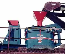
VSI crushers use a different approach involving a high speed rotor with wear resistant tips and a crushing chamber designed to 'throw' the rock against. The VSI crushers utilize velocity rather than surface force as the predominant force to break rock. In its natural state, rock has a jagged and uneven surface. Applying surface force (pressure) results in unpredictable and typically non-cubical resulting particles. Utilizing velocity rather than surface force allows the breaking force to be applied evenly both across the surface of the rock as well as through the mass of the rock. Rock, regardless of size, has natural fissures (faults) throughout its structure. As rock is 'thrown' by a VSI rotor against a solid anvil, it fractures and breaks along these fissures. Final particle size can be controlled by 1) the velocity at which the rock is thrown against the anvil and 2) the distance between the end of the rotor and the impact point on the anvil. The product resulting from VSI crushing is generally of a consistent cubical shape such as that required by modern Superpave highway asphalt applications. Using this method also allows materials with much higher abrasiveness to be crushed than is capable with an HSI and most other crushing methods.
VSI crushers generally utilize a high speed spinning rotor at the center of the crushing chamber and an outer impact surface of either abrasive resistant metal anvils or crushed rock. Utilizing cast metal surfaces 'anvils' is traditionally referred to as a "shoe and anvil VSI". Utilizing crushed rock on the outer walls of the crusher for new rock to be crushed against is traditionally referred to as "rock on rock VSI". VSI crushers can be used in static plant set-up or in mobile tracked equipment.
Mineral sizers
Mineral sizers are a variety of roll crushers which use two rotors with large teeth, on small diameter shafts, driven at a low speed by a direct high torque drive system. This design produces three major principles which all interact when breaking materials using sizer technology. The unique principles are the three-stage breaking action, the rotating screen effect, and the deep scroll tooth pattern.
The three-stage breaking action: initially, the material is gripped by the leading faces of opposed rotor teeth. These subject the rock to multiple point loading, inducing stress into the material to exploit any natural weaknesses. At the second stage, material is broken in tension by being subjected to a three-point loading, applied between the front tooth faces on one rotor, and rear tooth faces on the other rotor. Any lumps of material that still remain oversize, are broken as the rotors chop through the fixed teeth of the breaker bar, thereby achieving a three dimensional controlled product size.
The rotating screen effect: The interlaced toothed rotor design allows free flowing undersize material to pass through the continuously changing gaps generated by the relatively slow moving shafts.
The deep scroll tooth pattern: The deep scroll conveys the larger material to one end of the machine and helps to spread the feed across the full length of the rotors. This feature can also be used to reject oversize material from the machine.[7]
Crusher Bucket

A crusher bucket is an attachment for hydraulic excavators. Its way of working consists on a bucket with two crushing jaws inside, one of them is fixed and the other one moves back and forth relative to it, as in a jaw crusher. They are manufactured with a high inertia power train, circular jaw movement and an antiestagnation plate, which prevents large shredding pieces from getting stuck in the bucket's mouth, not allowing them to enter the crushing jaws. They have also the crushing jaws placed in a cross position. This position together with its circular motion gives these crusher buckets the faculty of grinding wet material.

Technology
For the most part advances in crusher design have moved slowly. Jaw crushers have remained virtually unchanged for sixty years. More reliability and higher production have been added to basic cone crusher designs that have also remained largely unchanged. Increases in rotating speed have provided the largest variation. For instance, a 48-inch (120 cm) cone crusher manufactured in 1960 may be able to produce 170 tons/h of crushed rock, whereas the same size crusher manufactured today may produce 300 tons/h. These production improvements come from speed increases and better crushing chamber designs.
The largest advance in cone crusher reliability has been seen in the use of hydraulics to protect crushers from being damaged when uncrushable objects enter the crushing chamber. Foreign objects, such as steel, can cause extensive damage to a cone crusher, and additional costs in lost production. The advance of hydraulic relief systems has greatly reduced downtime and improved the life of these machines.
See also
| Wikimedia Commons has media related to Rock crushers. |
- Ball mill for further reduction to powder
- Car crusher
- Compactor
- Jaques Limited Australian jaw crusher manufacturer
- Mill (grinding)
- Scrap metal shredder
- Stamp mill
References
- "Science Museum - Home - Atmospheric engine by Francis Thompson, 1791". www.sciencemuseum.org.uk. Retrieved 2009-07-06.
- James, Burke (1978). "Chapter 6. Fuel to the Flame". Connections, UK ed. "Connections: Alternative History of Technology" (Time Warner International/Macmillan 1978) (ninth, pbk ed.). Little, Brown and Company (North America) / Macmillan, London. p. 304. ISBN 978-0-316-11681-7.
by 1600, England was facing an acute timber crises, thanks largely to the increase in glass production
- Burke, James, "Connections", page 167
- Burke, James, "Connections", page 168
- Burke, James, "Connections", page 170
- Clark, Ronald W. (1985). "page 63". Works of Man: History of Invention and Engineering, From the Pyramids to the Space Shuttle (1st American Edition. 8"x10" Hard cover ed.). Viking Penguin,Inc., New York, NY, U.S.A., (1985). pp. 352 (indexed). ISBN 9780670804832.
Within a few years, however, the cost was reduced by nine-tenths as it was found cast-iron cylinders could be produced with sufficient accuracy.
- MMD Group - http://www.mmdsizers.com/products/sizers