Control valve
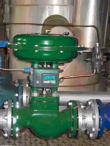
A control valve is a valve used to control fluid flow by varying the size of the flow passage as directed by a signal from a controller.[1] This enables the direct control of flow rate and the consequential control of process quantities such as pressure, temperature, and liquid level.
In automatic control terminology, a control valve is termed a "final control element".
Operation

The opening or closing of automatic control valves is usually done by electrical, hydraulic or pneumatic actuators. Normally with a modulating valve, which can be set to any position between fully open and fully closed, valve positioners are used to ensure the valve attains the desired degree of opening.
Air-actuated valves are commonly used because of their simplicity, as they only require a compressed air supply, whereas electrically-operated valves require additional cabling and switch gear, and hydraulically-actuated valves required high pressure supply and return lines for the hydraulic fluid.
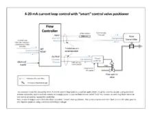
The pneumatic control signals are traditionally based on a pressure range of 3-15psi (0.2-1.0 bar), or more commonly now, an electrical signal of 4-20mA for industry, or 0-10V for HVAC systems. Electrical control now often includes a "Smart" communication signal superimposed on the 4-20mA control current, such that the health and verification of the valve position can be signalled back to the controller. The HART, Fieldbus Foundation, and Profibus are the most common protocols.
An automatic control valve consists of three main parts in which each part exist in several types and designs:
- Valve actuator - which moves the valve's modulating element, such as ball or butterfly.
- Valve positioner - Which ensures the valve has reached the desired degree of opening. This overcomes the problems of friction and wear.
- Valve body - in which the modulating element, a plug, globe, ball or butterfly, is contained.
Control action


Taking the example of an air-operated valve, there are two control actions possible:
- "Air or current to open" - The flow restriction decreases with increased control signal value.
- "Air or current to close" - The flow restriction increases with increased control signal value.
There can also be failure to safety modes:
- Air or control signal failure to close" - On failure of compressed air to the actuator, the valve closes under spring pressure or by backup power.
- Air or control signal failure to open" - On failure of compressed air to actuator, the valve opens under spring pressure or by backup power.
The modes of failure operation are requirements of the failure to safety process control specification of the plant. In the case of cooling water it may be to fail open, and the case of delivering a chemical it may be to fail closed.
Valve positioners
The fundamental function of a positioner is to deliver pressurized air to the valve actuator, such that the position of the valve stem or shaft corresponds to the set point from the control system. Positioners are typically used when a valve requires throttling action. A positioner requires position feedback from the valve stem or shaft and delivers pneumatic pressure to the actuator to open and close the valve. The positioner must be mounted on or near the control valve assembly. There are three main categories of positioners, depending on the type of control signal, the diagnostic capability, and the communication protocol: pneumatic analog and digital.[2]
Processing units may use pneumatic pressure signaling as the control set point to the control valves. Pressure is typically modulated between 20.7 to 103 kPa (3 to 15 psig) to move the valve from 0 to 100% position. In a common pneumatic positioner the position of the valve stem or shaft is compared with the position of a bellows that receives the pneumatic control signal. When the input signal increases, the bellows expands and moves a beam. The beam pivots about an input axis, which moves a flapper closer to the nozzle. The nozzle pressure increases, which increases the output pressure to the actuator through a pneumatic amplifier relay. The increased output pressure to the actuator causes the valve stem to move. Stem movement is fed back to the beam by means of a cam. As the cam rotates, the beam pivots about the feedback axis to move the flapper slightly away from the nozzle. The nozzle pressure decreases and reduces the output pressure to the actuator. Stem movement continues, backing the flapper away from the nozzle until equilibrium is reached. When the input signal decreases, the bellows contracts (aided by an internal range spring) and the beam pivots about the input axis to move the flapper away from the nozzle. Nozzle pressure decreases and the relay permits the release of diaphragm casing pressure to the atmosphere, which allows the actuator stem to move upward. Through the cam, stem movement is fed back to the beam to reposition the flapper closer to the nozzle. When equilibrium conditions are obtained, stem movement stops and the flapper is positioned to prevent any further decrease in actuator pressure.[2]
The second type of positioner is an analog I/P positioner. Most modern processing units use a 4 to 20 mA DC signal to modulate the control valves. This introduces electronics into the positioner design and requires that the positioner convert the electronic current signal into a pneumatic pressure signal (current-to-pneumatic or I/P). In a typical analog I/P positioner, the converter receives a DC input signal and provides a proportional pneumatic output signal through a nozzle/flapper arrangement. The pneumatic output signal provides the input signal to the pneumatic positioner. Otherwise, the design is the same as the pneumatic positioner[2]
While pneumatic positioners and analog I/P positioners provide basic valve position control, digital valve controllers add another dimension to positioner capabilities. This type of positioner is a microprocessor-based instrument. The microprocessor enables diagnostics and two-way communication to simplify setup and troubleshooting.
In a typical digital valve controller, the control signal is read by the microprocessor, processed by a digital algorithm, and converted into a drive current signal to the I/P converter. The microprocessor performs the position control algorithm rather than a mechanical beam, cam, and flapper assembly. As the control signal increases, the drive signal to the I/P converter increases, increasing the output pressure from the I/P converter. This pressure is routed to a pneumatic amplifier relay and provides two output pressures to the actuator. With increasing control signal, one output pressure always increases and the other output pressure decreases
Double-acting actuators use both outputs, whereas single-acting actuators use only one output. The changing output pressure causes the actuator stem or shaft to move. Valve position is fed back to the microprocessor. The stem continues to move until the correct position is attained. At this point, the microprocessor stabilizes the drive signal to the I/P converter until equilibrium is obtained.
In addition to the function of controlling the position of the valve, a digital valve controller has two additional capabilities: diagnostics and two-way digital communication.[2]
Widely used communication protocols include HART, FOUNDATION fieldbus, and PROFIBUS.
Advantages of placing a smart positioner on a control valve:
1. Automatic calibration and configuration of positioner. 2. Real time diagnostics. 3. Reduced cost of loop commissioning, including installation and calibration. 4. Use of diagnostics to maintain loop performance levels. 5. Improved process control accuracy that reduces process variability.
Types of control valve
Control valves are classified based on a number of attributes and feature. Like
1. Based on the pressure drop profile:
- High recovery valve - These valves typically regain most of static pressure drop from inlet to vena contracta at outlet. These valve are characterised with lower recovery coefficient. Examples of high recovery valve - butterfly valve, ball valve, plug valve, gate valve etc. - Low recovery valve - These valve typically regain very less of static pressure drop from inlet to vena contracta at outlet. These valve are characterised with higher recovery coefficient. Example of low recovery valve - globe valve, angle valve
2. Based on the movement profile of the controlling element:
- Sliding stem - Here the valve stem / plug moves in a linear straight line motion Examples - Globe valve, angle valve, wedge type gate valve - Rotary valve - Here the valve disc undergoes a rotary motion Examples - Butterfly valve, ball valve
3. Based on the functionality:
- Control valve - Here the valve controls flow parameters proportional to input signal received from central control system. Example - globe valve, angle valve, ball valve - Shut-off / On-off valve - Here the valve is either full open or full close Example - gate valve, ball valve, globe valve, angle valve, pinch valve, diaphragm valve etc. - Check valve - Here the valve allows flow only in a single direction - Steam conditioning valve - These valve regulate the pressure and temperature profile of inlet media to required parameters at outlet. Examples - turbine bypass valve, process steam letdown station etc. - Spring loaded Safety valve - These valve have closed to a pretensive force of spring, which retract to open when the inlet pressure is equal the spring force.
4. Based on the actuating medium:
- Manual valve - The valve are actuated by hand wheel - Pneumatic valve - The valve are actuated using compressible medium like air, hydrocarbon, nitrogen etc.. Typically the actuator could be spring diaphragm type, piston cylinder type or piston-spring type - Hydraulic valve - The valve actuated by non-compressible medium like water or oil - Electric valve - The valve actuated by electric motor
A huge variety of valve types and control operation exist. However, there are two main forms of action; the sliding stem and the rotary action.
The most common and versatile types of control valves are sliding-stem globe, V-notch ball, butterfly and angle types. Their popularity derives from rugged construction and the many options available that make them suitable for a variety of process applications.[3] Control valve bodies may be categorized as below:[2]
List of common types of control valve
- Sliding Stem
- Globe valve – Type of device for blocking or regulating the flow of fluids
- Angle body valve
- Angle seat piston valve
- Rotary
- Other
See also
- Check valve
- Control engineering – Engineering discipline that applies automatic control theory to design systems with desired behaviors
- Control system
- Distributed control system – Computerized control systems with distributed decision-making
- Fieldbus Foundation
- Flow control valve – valve that regulates the flow or pressure of a fluid
- Highway Addressable Remote Transducer Protocol, also known as HART Protocol
- Instrumentation
- PID controller – control loop feedback mechanism
- Process control
- Profibus
- SCADA, also known as Supervisory control and data acquisition system
References
- Instrument Society of America Standard S561.1, 1976. as reproduced in the "Fisher control valve handbook" fourth edition 1977.
- Emerson Automation Solutions (2017). "Control Valve Handbook" (PDF) (5th ed.). Fischer Controls International LLC. Retrieved 2019-05-04.
- Hagen, S. (2003) "Control valve technology" Plant Services
External links
- Process Instrumentation (Lecture 8): Control valves Article from a University of South Australia website.
- Control Valve Sizing Calculator Control Valve Sizing Calculator to determine Cv for a valve.