Air-blast injection
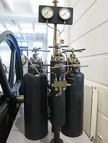
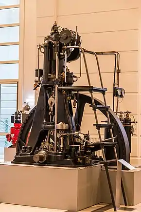
Air-blast injection is a historical direct injection system for Diesel engines. Unlike modern designs, air-blast injected Diesel engines do not have an injection pump. A simple low-pressure fuel-feed-pump is used instead to supply the injection nozzle with fuel. At injection, a blast of compressed air presses the fuel into the combustion chamber, hence the name air-blast injection. The compressed air comes from compressed-air tanks which feed the injection nozzle. A large crankshaft-driven compressor is used to re-fill these tanks; the size of the compressor and the low rotational frequency of the engine's crankshaft means that air-blast injected Diesel engines are huge in size and mass, this, combined with the problem that air-blast injection does not allow for quick load alteration[1] makes it only suitable for stationary applications and watercraft. Before the invention of precombustion chamber injection, air-blast injection was the only way a properly working internal air fuel mixture system could be built, required for a Diesel engine. During the 1920s,[2] air-blast injection was rendered obsolete by superior injection system designs that allowed much smaller but more powerful engines.[3] Rudolf Diesel was granted a patent on air-blast injection in November 1893 (DRP 82 168).[4]
History
The air-blast injection system was first used by George Bailey Brayton in 1872 for a two-stroke gas engine. Rudolf Diesel wanted to build an engine with direct injection for which he tried using accumulating in 1893.[5] Due to the highly viscous fuels Diesel used and thermal afterburning occurring, the principle of accumulating did not work sufficiently. Therefore, Diesel had to improve the injection system. German engineer Friedrich Sass says that Diesel knew about Brayton's invention and that it is therefore very likely that Diesel decided to replace his own inferior injection system with an air-blast injection system similar to Brayton's.[6] Diesel did so in February 1894,[4] because he could not come up with a better solution, however, Diesel wanted to replace the air-blast injection system with a superior system ever since; an improved accumulating system which allowed for direct injection without a huge compressor was patented by Diesel and Rudolf Brandstetter in 1905.[7] Nevertheless, this improved system was still insufficient and Diesel considered direct injection without a huge compressor „unfeasible“. It took another ten years for the first working direct injected Diesel engines which were not air-blast injected to show up in 1915;[8] the precombustion chamber, which made motor vehicle Diesel engines possible, had been invented in 1909.[9]
Design
Atomiser design
Initially, sieve-type amtomisers were used for the injections nozzles, until the sieves were widely replaced by discs.[1] Also, ring-type atomisers were used for some engines.[10]
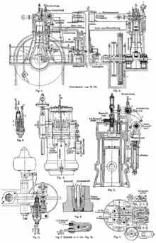
The ring-type atomiser is based on the principle of different air velocities occurring inside the nozzle, which force the fuel to mix up with air.[11] Disc-type atomisers have small perforated discs placed above each other with small gaps in between (as seen in Fig. 6 in the sectional drawing on the right). The discs are slightly misaligned to increase constriction. Depending on the capacity of the engine and, therefore, quantity of injected fuel, either two, three or four dics are used per injection nozzle. The disc material depends on the fuel type. In general, bronze casting and phosphor bronze casting are used; for engines running on coal tar, the discs are usually made from steel.[12]
For engines with disc-type atomisers, the injection pressure should be in sync with the rotational frequency of the crankshaft. This means that with an increase in rotational frequency, the air pressure must be increased as well.[13] Usually, at injection, 97% air and 3% fuel are getting injected through the injection nozzle.[8] The injection pressure is between 5 and 7 MPa which limits the rotational frequency. Also, with increasing engine load, the injection pressure must be reduced to prevent misfire.[13]
Neither disc hole diameter calculation nor the proper size of the discs were known engineering knowledge at the beginning of the 20th Century. The disc designs were usually based on the engineers' experience. While big holes require a lot of compressed air and therefore consume more engine power, holes being too small reduce the engine power output. Julius Magg recommends a disc hole diameter depending on the indicated cylinder power output: . is the hole diameter in millimetres, is the power output in PS.[14]
Nozzle layout
In the early 20th Century, two different injection nozzle designs for air-blast injected engines were common: The open nozzle and the closed nozzle design.[15]
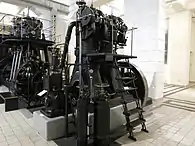
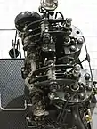
The closed nozzle design was the initial and most common design, it is usually found in vertical engines (such as the Langen & Wolf engine as seen on the right). It can be used for both two- and four-stroke engines. The injection nozzle is supplied with fuel from the fuel-feed-pump while constantly being fed with compressed air from the compressed-air tank. This means that the fuel-feed-pump has to overcome the resistance caused by the injection-air-pressure. A separate cam on the camshaft (as seen in Fig. 5 and on the two-cylinder Johann-Weitzer-engine on the right) would activate the injection valve so the compressed air would then press the fuel into the combustion chamber. Before the injection valve opens, neither fuel nor compressed air can enter the combustion chamber.[16] The closed nozzle design allowed for a good air-fuel-mixture at the time which made it very useful for high capacity engines. This also resulted in lower fuel consumption compared to the open nozzle design. Biggest disadvantages were the higher manufacturing cost and the injection nozzle restrictions that made designing engines with horizontal cylinders considerably difficult,[17] since in horizontal cylinder engines, compressed air can easily enter the cylinder without pressing a sufficient quantity of fuel into the combustion chamber which leads to engine misfire or postignition.[18]
The open nozzle design was mostly used for engines with horizontal cylinders and unusual for engines with vertical cylinders. It can only be used for four-stroke engines.[17] Like in the closed nozzle design, the fuel is fed to the injection nozzle. However, the injection valve only prevents compressed air from entering the cylinder; the fuel constantly enters a prechamber above the combustion chamber in the cylinder. Between prechamber and combustion chamber, the disc-type atomisers are placed to separate the chambers from each other. At injection, the compressed air would then press the fuel through the disc-type atomisers into the combustion chamber.[19] Manufacturing engines featuring the open nozzle design was considerably cheaper and easier than making them with a closed nozzle design. It also allows for using tar as fuel. However, fuel supply is insufficient and at the beginning of the injection, too much fuel enters the combustion chamber which causes too much pressure buildup inside the cylinder. This, as well as the problem that it is impossible to supply high capacity engines sufficiently with fuel, means, that the open nozzle design can only be used for smaller engines.[17]
References
- Rüdiger Teichmann, Günter P. Merker (publisher): Grundlagen Verbrennungsmotoren : Funktionsweise, Simulation, Messtechnik , 7th issue, Springer, Wiesbaden, 2014, ISBN 978-3-658-03195-4, p. 381.
- Rüdiger Teichmann, Günter P. Merker (publisher): Grundlagen Verbrennungsmotoren : Funktionsweise, Simulation, Messtechnik , 7th issue, Springer, Wiesbaden, 2014, ISBN 978-3-658-03195-4, p. 382.
- Anton Pischinger, Otto Cordier: Gemischbildung und Verbrennung im Dieselmotor, Springer, Wien, 1939, ISBN 978-3-7091-9724-0, p. 1
- Rudolf Diesel: Die Entstehung des Dieselmotors, Springer, Berlin 1913, ISBN 978-3-642-64940-0, p. 21
- MAN Nutzfahrzeuge AG: Leistung und Weg: Zur Geschichte des MAN Nutzfahrzeugbaus.Springer, Berlin / Heidelberg, 1991, ISBN 978-3-642-93490-2. p. 440
- Friedrich Sass: Geschichte des deutschen Verbrennungsmotorenbaus von 1860 bis 1918, Springer, Berlin/Heidelberg 1962, ISBN 978-3-662-11843-6, p. 414
- MAN Nutzfahrzeuge AG: Leistung und Weg: Zur Geschichte des MAN Nutzfahrzeugbaus.Springer, Berlin / Heidelberg, 1991, ISBN 978-3-642-93490-2. p. 417
- MAN Nutzfahrzeuge AG: Leistung und Weg: Zur Geschichte des MAN Nutzfahrzeugbaus.Springer, Berlin / Heidelberg, 1991, ISBN 978-3-642-93490-2. p. 419
- Friedrich Sass: Bau und Betrieb von Dieselmaschinen: Ein Lehrbuch für Studierende. Erster Band: Grundlagen und Maschinenelemente, 2nd issue, Springer, Berlin / Heidelberg, 1948, ISBN 9783662004197, p. 94 & 95
- Julius Magg: Die Steuerungen der Verbrennungskraftmaschinen, Springer, Berlin, 1914, ISBN 978-3-642-47608-2, p. 270
- Julius Magg: Die Steuerungen der Verbrennungskraftmaschinen, Springer, Berlin, 1914, ISBN 978-3-642-47608-2, p. 271
- Julius Magg: Die Steuerungen der Verbrennungskraftmaschinen, Springer, Berlin, 1914, ISBN 978-3-642-47608-2, p. 265
- Julius Magg: Die Steuerungen der Verbrennungskraftmaschinen, Springer, Berlin, 1914, ISBN 978-3-642-47608-2, p. 269
- Julius Magg: Die Steuerungen der Verbrennungskraftmaschinen, Springer, Berlin, 1914, ISBN 978-3-642-47608-2, p. 274
- Julius Magg: Die Steuerungen der Verbrennungskraftmaschinen, Springer, Berlin, 1914, ISBN 978-3-642-47608-2, p. 261
- Julius Magg: Die Steuerungen der Verbrennungskraftmaschinen, Springer, Berlin, 1914, ISBN 978-3-642-47608-2, p. 263
- Julius Magg: Die Steuerungen der Verbrennungskraftmaschinen, Springer, Berlin, 1914, ISBN 978-3-642-47608-2, p. 280
- Julius Magg: Die Steuerungen der Verbrennungskraftmaschinen, Springer, Berlin, 1914, ISBN 978-3-642-47608-2, p. 268
- Julius Magg: Die Steuerungen der Verbrennungskraftmaschinen, Springer, Berlin, 1914, ISBN 978-3-642-47608-2, p. 275
