4000-series integrated circuits
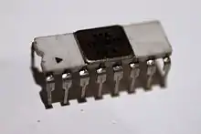
The 4000 series is a CMOS logic family of integrated circuits (ICs) first introduced in 1968 by RCA.[1] Almost all IC manufacturers active during this initial era fabricated models for this series. It is still in use today.

History
The 4000 series was introduced as the CD4000 COS/MOS series in 1968 by RCA[1] as a lower power and more versatile alternative to the 7400 series of transistor-transistor logic (TTL) chips. The logic functions were implemented with the newly introduced Complementary Metal–Oxide–Semiconductor (CMOS) technology. While initially marketed with "COS/MOS" labeling by RCA (which stood for Complementary Symmetry Metal-Oxide Semiconductor), the shorter CMOS terminology emerged as the industry preference to refer to the technology.[2] The first chips in the series were designed by a group led by Albert Medwin.[3]
Wide adoption was initially hindered by the comparatively lower speeds of the designs compared to TTL based designs. Speed limitations were eventually overcome with newer fabrication methods, leaving the older TTL chips to be phased out. The series was extended in the late 1970s and 1980s with new models that were given 45xx and 45xxx designations, but are usually still regarded by engineers as part of the 4000 series. In the 1990s, some manufacturers (e.g. Texas Instruments) ported the 4000 series to newer HCMOS based designs to provide greater speeds.
Design considerations
The 4000 series facilitates simpler circuit design through relatively low power consumption, a wide range of supply voltages, and vastly increased load-driving capability (fanout). This makes the series ideal for use in prototyping LSI designs. While TTL based design is similarly modular, it requires meticulous planning of a circuit's electrical load characteristics. Buffered models can accommodate higher electrical currents, but have a greater risk of introducing unwanted feedback.[4][5] Many models contain a high level of integration, including fully integrated 7-segment display counters, walking ring counters, and full adders.
Common chips


- One-input gates
- 4049 – Hex inverter gate with strong output drivers (capable of driving up to four 74LS inputs).
- 4050 – Hex buffer gate with strong output drivers (capable of driving up to four 74LS inputs).
- 40106 – Hex inverter gate with schmitt-trigger inputs.
- 40109 – Quad buffer gate with dual power-rails (voltage-level translation).
- 4504 – Hex buffer gate with dual power-rails (voltage-level translation).
- Two-input gates
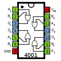
- 4001 – Quad 2-input NOR gate.
- 4011 – Quad 2-input NAND gate.
- 4070 – Quad 2-input XOR gate.
- 4071 – Quad 2-input OR gate.
- 4077 – Quad 2-input XNOR gate.
- 4081 – Quad 2-input AND gate.
- 4093 – Quad 2-input NAND gate with schmitt-trigger inputs.
- 40107 – Dual 2-input NAND gate with 136 mA open-drain output drivers in 8-pin IC.
- Three-input, four-input, eight-input gate chips are available too.
- Flip-flops
- 4013 – Dual D-Type Flip Flop. Each flip-flop has independent data, Q, /Q, clock, reset, set.
- 40174 – Hex D-Type Flip Flop. Each flip-flop has independent data and Q. All share clock and reset.
- 40175 – Quad D-Type Flip Flop. Each flip-flop has independent data, Q, /Q. All share clock and reset.
- Counters
- 4017 – Decade counter to 10-output decoder.
- 4026 – Decade counter to 7-segment digit decoder.
- 40110 – Up/Down decade counter to 7-segment display decoder with 25 mA output drivers.
- 40192 – Up/Down decade counter with 4-bit BCD preset.
- 40193 – Up/Down binary counter with 4-bit binary preset.
- Decoders
- 4028 – 4-bit BCD to 10-output decoder (can be used as 3-bit binary to 8-output decoder)
- 4511 – 4-bit BCD to 7-segment display decoder with 25 mA output drivers.
- Timers
- 4047 – Monostable/Astable multivibrator with external RC oscillator.
- 4060 – 14-bit ripple counter with external RC or crystal oscillator (long duration) (schmitt-trigger inputs) (can be used with 32.768 kHz crystal)
- 4541 – 16-bit ripple counter with external RC oscillator (long duration).
- Analog
- 4051 – Single 8-channel analog mux.
- 4066 – Quad SPST analog switch.
See also
References
- "1963: Complementary MOS Circuit Configuration is Invented". Computer History Museum. Archived from the original on July 23, 2019.
- "Wright, Maury. Milestones That Mattered: CMOS pioneer developed a precursor to the processor EDN, 6/22/2006". Archived from the original on 2007-09-27. Retrieved 2006-07-01.
- R. Jacob Baker (2010). CMOS: Circuit Design, Layout, and Simulation (3rd ed.). John Wiley & Sons. p. 7. ISBN 978-1-118-03823-9.
- Understanding Buffered and Unbuffered CD4xxxB Series Device Characteristics. Texas Instruments
- Lancaster, Don. CMOS Cookbook, ISBN 0-672-21398-2
Further reading
- Periodicals
- New low-voltage COS/MOS IC's (CD4000A); RCA Engineer; Vol 17 No 1; June 1971 to July 1971; Pages 40-45.
- 15 articles about COS/MOS IC's; RCA Engineer; Vol 18 No 4; December 1972 to January 1973.
- Books
- CMOS Sourcebook; 1st Ed; Newton Braga; Prompt Press; 390 pages; 2001; ISBN 978-0790612348.
- CMOS Cookbook; 2nd Ed; Don Lancaster, Howard Berlin; Elsevier; 512 pages; 1988; ISBN 978-0750699433. (1st Ed in 1977)
- Second Book of CMOS IC Projects; 1st Ed; R.A. Penfold; Bernard Babani Publishing; 127 pages; 1979; ISBN 0900162783. (archive)
- 50 CMOS IC Projects; 1st Ed; R.A. Penfold; Bernards Publishing; 112 pages; 1977; ISBN 978-0900162640. (archive)
- RCA COS/MOS IC Manual; 170 pages; 1979; CMS-272.
- RCA COS/MOS IC Manual; TBD pages; 1971; CMS-270.
- Historical Databooks
- RCA COS/MOS Databook; 649 pages; 1975; SSD-203C.
- RCA CMOS Databook; 798 pages; 1983; SSD-250C.
- Motorola CMOS Databook; 560 pages; 1988.
- National CMOS Databook; 930 pages; 1981.
External links
| Wikimedia Commons has media related to 4000 Series. |
- Understanding 4000-series digital logic ICs – Nuts and Volts magazine
- Thorough list of 4000-series ICs – Electronics Club
- 4000-series logic and analog circuitry – Analog Devices
